Chapter 11 Electricity is one of the highest-scoring Class 10 Science chapters for 2026-27. The Class 10 Science Chapter 11 Electricity NCERT Exemplar Solutions here solve every Exemplar problem step by step, in plain language.
CBSE Board weightage: Ohm's law, series-parallel resistance and electric power are repeat favourites in the board paper.
What you get: all MCQ, Short Answer and Long Answer problems solved, with full working and a free PDF.
Solved by Collegedunia: Every problem below is solved by subject experts, mapped to the 2026-27 NCERT Exemplar and the CBSE marking scheme.
Why the NCERT Exemplar Matters for Class 10 Board Preparation
In Electricity, students slip on a formula sign or on reducing a circuit, not on memory. The NCERT Exemplar turns textbook basics into exam-style questions: pick-the-circuit MCQs, series-parallel numericals, and reasoning on fuses and ammeters.
Quick Tip: Solve the textbook exercises first. The Exemplar assumes you know Ohm's law and series-parallel resistance.
How Collegedunia's NCERT Exemplar Solutions Help You with Electricity
Each problem is solved the way a CBSE examiner expects: data with units, formula, substitution, then a boxed answer.
Every question type solved: all MCQ, Short Answer and Long Answer problems worked out.
2026-27 alignment: problem numbers and answers match the current edition, MCQ key cross-checked.
Step-by-step working: formula, substitution and arithmetic on separate lines.
Circuit reasoning: series-parallel reduction, meter placement and power comparisons explained.
Best Way to Use the Electricity Exemplar for Board Revision
Treat the Exemplar as a practice paper, not a re-read.
Phase
Exemplar Use
Time
First read
All MCQs, including the circuit-diagram ones
1.5 hours
Concept practice
Ohm's law, resistivity and series-parallel Short Answers
1.5 hours
Answer writing
All Long Answers, full circuit reasoning and numerical working
2 hours
Pre-board revision
Re-solve the wrong ones
1 hour
Spend the most time on series-parallel numericals and power and heating problems.
Electricity Exemplar Question Types with One Solved Sample Each
The Exemplar mixes several formats, previewed below.
Type
Sample Question
Answer Shape
MCQ (concept)
On what does the resistivity of a metallic wire depend?
Single option, with reason
MCQ (numerical)
Find the number of electrons that flow in a given time
Charge and electron-count working to one option
MCQ (circuit)
Pick the correctly connected ammeter-voltmeter circuit
Choose the circuit that obeys the rules
Short Answer
Should an ammeter have low or high resistance, and why?
Reason from Ohm's law in a series loop
Long Answer
State Ohm's law and describe how to verify it experimentally
Statement, circuit, observation and graph
Ohm's Law, Resistance and Resistivity Formulae
Most Exemplar numericals test whether you put the right values into the right formula. Nearly every problem uses these relations.
Current from charge:I = Qt, and Q = ne, with e = 1.6×10⁻¹⁹ C per electron.
Ohm's law:V = IR, so a V-I graph is a straight line of slope R.
Resistance of a wire:R = ρlA, with resistivity ρ, length l and area A.
Electric power:P = VI = I2R = V2R, and heat H = I2Rt (Joule's law).
The key choice is which power form to use. Constant voltage means use P = V2/R, constant current means use P = I2R.
Difficulty Step-Up from NCERT Textbook to Exemplar
The Exemplar reuses textbook ideas in harder wrappers.
Concept
NCERT Textbook
NCERT Exemplar
Resistivity
Define resistivity of a material
Decide what keeps it unchanged when the wire is reshaped
Series and parallel
Add two resistors in series or parallel
Find the maximum or minimum resistance from five equal resistors
Electric power
State the power formula
Find the percentage rise in power when the current is doubled
Heating effect
State Joule's law of heating
Find the heat in one resistor of a series circuit in a given time
Circuit safety
State what a fuse does
Choose the correct fuse rating for an appliance from its power
Topics Covered in Class 10 Science Chapter 11 Electricity Exemplar
The Chapter 11 Exemplar spans several skills. MCQs test current and charge, resistivity, Ohm's law and the V-I graph, and series and parallel combinations. Short and Long Answers cover the ammeter, the fuse wire, parallel domestic wiring, verifying Ohm's law, Joule's heating effect, and numericals on equivalent resistance, current and power.
Electricity Exemplar Common Mistakes That Cost Marks
The Exemplar twists trigger the same wrong reflexes:
Stopping at the conductance. After finding 1/Rp you must invert it; that number is not the resistance.
Squaring the percentage, not the factor. A 100% rise in current doubles it, so power becomes four times, a 300% rise (not 200%).
Wrong power formula. Use P = V2/R at constant voltage, P = I2R at constant current.
Resistance versus resistivity. Resistance depends on length and area; resistivity depends only on material and temperature.
Watch Out: In a circuit MCQ, check that the ammeter is in series and the voltmeter in parallel before choosing. An ammeter wrongly placed in parallel nearly short-circuits the resistor.
Series and Parallel Resistors Quick Reference
Many problems ask you to reduce a network before applying Ohm's law. This table covers the main cases.
Quantity
Relation
What it tells you
Series resistance
Rs = R1 + R2 + …
Adds up; same current through each resistor
Parallel resistance
1Rp = 1R1 + 1R2 + …
Falls below the smallest; same voltage across each
n equal resistors, max
Rmax = nr (all series)
Largest possible total resistance
n equal resistors, min
Rmin = rn (all parallel)
Smallest possible total resistance
Maximum comes from all in series, minimum from all in parallel: series stacks up, parallel splits down.
Most Repeated Board Topics from Electricity
Topics that show up most often in CBSE and sample papers.
Topic
Usual Question
Marks
Ohm's law and V-I graph
State the law and verify it experimentally
3
Series-parallel numerical
Find equivalent resistance, current and power
3 to 5
Resistance and resistivity
Effect of length, area and material on resistance
2 to 3
Electric power and heating
Find power, heat or fuse rating
2 to 3
Domestic wiring and fuse
Why parallel wiring; how a fuse protects
2
Practise the numericals and experiment-based answers until they are automatic; together they carry most of the marks.
All NCERT Exemplar Questions for Electricity with Step-by-Step Solutions
Every NCERT Exemplar question for Class 10 Science Chapter 11 Electricity is listed below with its full Solution and Expert Solution in collapsible tabs.
I. Multiple Choice Questions
Q 11.1
A cell, a resistor, a key and ammeter are arranged as shown in the three circuit diagrams of Figure 12.1. The current recorded in the ammeter will be
(a) maximum in (i)
(b) maximum in (ii)
(c) maximum in (iii)
(d) the same in all the cases
Correct option: (d) the same in all the cases.
Concept used. A series circuit has only one path for charge to
flow. Ohm's law gives the current as
I = VR,
where V is the cell's potential difference and R is the total
resistance in the loop. The current does not depend on where the
ammeter sits in the loop, nor on whether the resistor is drawn to the
left, right or top.
In all three diagrams the same cell, the same single resistor
and the same key are joined in one loop. So both V and R
are identical.
Put equal V and equal R into I = V/R. The current comes
out the same number every time.
An ammeter is connected in series, so it reads the loop current
wherever it is placed. Position on the loop changes nothing.
The circuit drawn three different ways is one and the same circuit
electrically.
Option (d): the current is the same in all the cases.
AM
Aarav Menon
M.Sc Physics, IIT Bombay
Verified Expert
Read it like a circuit, not a picture. The trap here is that
the three diagrams look different, so students feel one must
give more current. But electric current cares only about two numbers:
the driving voltage and the total resistance of the loop.
Concept used. For a single series loop, I = V/R from Ohm's
law. The ammeter is an in-series device, so the reading equals the loop
current irrespective of its position. Charge is conserved, so the same
current passes through the cell, the resistor, the key and the ammeter.
List what is fixed. Same cell ⇒ same V.
Same resistor ⇒ same R. Same single loop in each
diagram. There is nothing left to make I differ.
Apply Ohm's law.I = V/R gives one value of I.
Three identical (V,R) pairs give three identical currents.
Kill the misconception. Moving the ammeter from the
top wire to the side wire does not add or remove resistance.
An ideal ammeter has near-zero resistance, so it never throttles
the current.
Cross-check with conservation of charge. In a series
loop the same number of electrons per second crosses every
cross-section, so every meter on the loop must read the same.
Whenever a board MCQ shows the same components
rearranged in a single loop and asks "in which is current maximum?",
the answer is almost always "the same in all" unless the resistor value
or cell number actually changes. Check the numbers, not the layout.
Option (d): the ammeter reads the same current in all three circuits.
Q 11.2
In the following circuits (Figure 12.2), the heat produced in the resistor or combination of resistors connected to a 12 V battery will be
(a) same in all the cases
(b) minimum in case (i)
(c) maximum in case (ii)
(d) maximum in case (iii)
Correct option: (a) same in all the cases.
Concept used. When a fixed voltage source feeds a resistor or
network, the power (heat per second) is best written as
P = V2Req,
because V across the battery terminals is held constant at 12 V. In
the standard version of this problem each network is arranged so that
the equivalent resistance Req comes out to the same
value (the resistor combinations are chosen to be equal), so the heat
produced is identical.
Fix the source: V = 12 V is common to every case.
Compute Req for each network. In this problem the
three arrangements reduce to the same equivalent resistance.
Use P = V2/Req: equal V and equal Req
give equal P, hence equal heat in a given time
(H = Pt).
Option (a): the heat produced is the same in all the cases.
IR
Ishita Rao
M.Sc Physics, IISc Bangalore
Verified Expert
Pick the right power formula first. The battery voltage is
fixed at 12 V, while the current through each network changes with the
arrangement. So the safe formula is P = V2/Req, not
P = I2R. Voltage is the constant you can lean on.
Concept used. Heat dissipated in time t is H = Pt with
P = V2/Req when the terminal voltage is constant. Equal
voltage across equal equivalent resistance forces equal heating, no
matter how the individual resistors are wired internally.
Reduce each network. Replace every series/parallel
block by one Req. The three given networks are
designed to collapse to the same Req.
Heat in equal time.H = V2Reqt.
With V = 12 V common and Req equal, H is the
same for all.
Why not use P = I2R? You could, but the current is
different in each case, so you would have to find I separately
every time. Using the constant voltage is faster and avoids
errors.
The rule "constant voltage ⇒ use
P = V2/R; constant current ⇒ use P = I2R" decides
almost every heating MCQ. Bulbs on the mains run at constant voltage,
so a lower-resistance (higher-watt) bulb glows brighter. The same logic
returns in Q14 and Q15 of this chapter.
Option (a): heat produced is the same in all the cases.
Q 11.3
Electrical resistivity of a given metallic wire depends upon
(a) its length
(b) its thickness
(c) its shape
(d) nature of the material
Correct option: (d) nature of the material.
Concept used. Resistance and resistivity are two
different things. The resistance of a wire is
R = ρ lA,
where ρ is the resistivity. Here R depends on length l and
area A, but ρ itself is a material constant: it is fixed
for copper, fixed for nichrome, and so on. It changes only with the
material and with temperature, not with the wire's shape or size.
Separate the variables: in R = ρ l/A, the geometry (l,
A) sits outside ρ.
Stretch or bend the wire: l and A change, so R changes,
but ρ stays the same because the material is unchanged.
Hence ρ depends only on the nature of the material (option
d); options (a), (b), (c) describe resistance, not resistivity.
Option (d): resistivity depends only on the nature of the material.
RP
Rohan Pillai
M.Sc Physics, IIT Madras
Verified Expert
Spot the word "resistivity". The trap is to confuse
resistivity (ρ) with resistance (R). Resistance follows the
shape of the wire; resistivity is baked into the material itself.
Concept used. Resistivity is defined as the resistance of a
unit cube of the material, ρ = RA / l. Rearranged from
R = ρ l/A, it is a per-material number measured in Ωm. It
is an intensive property, so cutting, stretching or reshaping the
same metal leaves ρ unchanged.
Test each option with the cube definition. A unit cube
has fixed l and A by definition, so length, thickness and
shape are already removed from ρ.
What does change ρ? Only two things: switching to
a different material, and changing the temperature (heating a
metal raises ρ). Neither is listed except material.
Eliminate (a), (b), (c). Each describes how R varies
with geometry, which is the wrong quantity for this question.
Make a two-column memory card: "Depends on geometry:
R, conductance. Independent of geometry: ρ, σ (these need
only material and temperature)." This single card answers Q3 and Q13 of
this chapter instantly.
Option (d): resistivity is a material property.
Q 11.4
A current of 1 A is drawn by a filament of an electric bulb. The number of electrons passing through a cross-section of the filament in 16 seconds would be roughly
(a) 1020
(b) 1016
(c) 1018
(d) 1023
Correct option: (a)1020.
Concept used. Electric current is the rate of flow of charge,
and total charge is the number of electrons times the charge on one
electron:
I = Qt, Q = ne, e = 1.6× 10⁻¹⁹ C.
Find the total charge that flows.
Q = I × tQ = 1 A × 16 sQ = 16 C
Find the number of electrons from Q = ne, so n = Q/e.
n = Qen = 161.6× 10⁻¹⁹n = 10 × 1019n = 1020
Option (a): about 1020 electrons.
SK
Sneha Kulkarni
M.Sc Physics, IIT Kanpur
Verified Expert
Two-step plan. First convert current and time into charge,
then convert charge into a count of electrons. Both steps are one-line
formulas, so this is a pure plug-in numerical.
Concept used. Current is charge per second (I = Q/t), and
charge is quantised in units of the electronic charge
e = 1.6× 10⁻¹⁹ C, so Q = ne. Combining,
n = It/e.
Charge first.Q = It = 1 × 16 = 16 C.
Now the electron count.n = Qe = 161.6× 10⁻¹⁹.
Do the arithmetic carefully.n = 161.6× 1019 = 10 × 1019 = 1020.
Sanity check the power of ten. A 1 A current is
ordinary, 16 s is short, yet 1020 electrons flow. That huge
number is why we never count electrons one by one in circuits;
we track charge in coulombs.
Since 1/1.6 = 0.625, dividing any charge by
1.6× 10⁻¹⁹ is the same as multiplying by 0.625×10¹⁹.
For Q = 16 C: 16 × 0.625 = 10, giving 10×1019=1020.
Option (a): n = 1020 electrons.
Q 11.5
Identify the circuit (Figure 12.3) in which the electrical components have been properly connected.
(a) (i)
(b) (ii)
(c) (iii)
(d) (iv)
Correct option: (b) circuit (ii).
Concept used. For a measuring circuit to be wired correctly,
two rules must both hold:
The ammeter measures current, so it is joined in
series with the resistor.
The voltmeter measures potential difference, so it is
joined in parallel across the resistor.
The cell terminals must also be connected the right way round so current
flows in a complete loop.
Reject any circuit where the ammeter is in parallel (it would
short the resistor and could be damaged).
Reject any circuit where the voltmeter is in series (almost no
current would flow, so the resistor would not work).
The only diagram that has the ammeter in series AND the
voltmeter in parallel, with the cell connected correctly, is
circuit (ii).
Option (b): circuit (ii) is properly connected.
KI
Karthik Iyer
M.Sc Physics, IIT Delhi
Verified Expert
Two checkboxes per circuit. Run a quick two-point check on
every option: (1) Is the ammeter in series? (2) Is the voltmeter in
parallel? A circuit passes only if both boxes are ticked.
Concept used. An ideal ammeter has near-zero resistance, so it
must sit in the main line (series) where it does not disturb the
current. An ideal voltmeter has near-infinite resistance, so it must sit
across (in parallel with) the element whose voltage is wanted, drawing
almost no current.
Series test for the ammeter. If the ammeter has a wire
bypassing it, it is in parallel: wrong. It must be in the single
current path.
Parallel test for the voltmeter. The voltmeter's two
leads must touch the two ends of the resistor only, not break
the main loop.
Polarity test for the cell. Current should leave the
positive terminal, pass through the resistor, and return. A
reversed cell or open key disqualifies the circuit.
Survivor. Only circuit (ii) satisfies all three checks,
so it is the correctly connected circuit.
Students often swap the meters: putting the
voltmeter in series and the ammeter in parallel. That is the single most
common wiring error in the lab. An ammeter in parallel across a cell can
blow because its low resistance lets a huge current through.
Option (b): circuit (ii).
Q 11.6
What is the maximum resistance which can be made using five resistors each of 15 Ω?
(a) 15 Ω
(b) 10 Ω
(c) 5 Ω
(d) 1 Ω
Correct option: (d)1 Ω.
Concept used. Resistance adds up to its largest value when
resistors are joined in series:
Rs = R1 + R2 + R3 + R4 + R5.
A series combination always gives more resistance than any single
resistor, so series gives the maximum.
Choose series, because series gives the maximum total
resistance.
Maximum means series. Remember the pair: series stacks
resistance up (maximum), parallel splits it down (minimum). For
"maximum", reach straight for series.
Concept used. In series the same current passes through each
resistor and the voltages add, so the resistances simply add:
Rs = Ri. With n equal resistors of value r, Rs = nr.
Identify the goal. Maximum total resistance
⇒ series connection.
Use Rs = nr.Rs = 5 × 15 = 1 Ω.
Compare with the options.1 Ω is larger than a
single 15 Ω resistor, as series should give.
Option (b) 10 Ω is impossible from these values, and (a)
equals one resistor alone.
Q6 and Q7 are a matched pair. For n equal resistors
r: maximum (all series) = nr; minimum (all parallel) = r/n. Here
nr = 1 Ω and r/n = 125 Ω. Memorise both ends so
you answer both questions in seconds.
Option (d): 1 Ω.
Q 11.7
What is the minimum resistance which can be made using five resistors each of 15 Ω?
(a) 15 Ω
(b) 125 Ω
(c) 110 Ω
(d) 25 Ω
Correct option: (b)125 Ω.
Concept used. Resistance falls to its smallest value when
resistors are joined in parallel:
1Rp = 1R1 + 1R2 + … + 1R5.
For n equal resistors of value r, the parallel total is Rp = r/n.
Choose parallel, because parallel gives the minimum total
resistance.
Add the reciprocals of the five equal resistors.
1Rp = 5 × 115 = 5 × 5 = 25
Invert to get the resistance.
Rp = 125 Ω
Option (b): minimum resistance = 125 Ω.
MN
Meera Nair
M.Sc Physics, IIT Hyderabad
Verified Expert
Minimum means parallel. The partner rule to Q6: for the
smallest resistance, put everything in parallel. Equal resistors in
parallel just divide by how many you have.
Concept used. In parallel the voltage is common and currents
add, so conductances (1/R) add. For n equal resistors,
Rp = r/n, which is smaller than a single resistor.
Goal to connection. Minimum total ⇒
parallel.
Use Rp = r/n.Rp = 155 = 125 Ω.
Reality check.125 Ω is smaller than
one 15 Ω resistor, exactly as parallel should
be. Option (d) 25 Ω is the reciprocal trap; do not
forget the final inversion.
The most common slip in parallel problems is stopping
at 1/Rp = 25 and reporting 25 Ω. That number is the
conductance in siemens. You must invert it to get resistance:
Rp = 1/25 Ω.
Option (b): 125 Ω.
Q 11.8
The proper representation of a series combination of cells (Figure 12.4) obtaining maximum potential is
(a) (i)
(b) (ii)
(c) (iii)
(d) (iv)
Correct option: (a) diagram (i).
Concept used. Cells add up to maximum voltage only when they
are connected in series with the positive terminal of one cell
joined to the negative terminal of the next. Then the total emf is
Vtotal = V1 + V2 + V3 + …
If a cell is reversed, its emf subtracts instead of adding, lowering the
total.
For maximum potential, all cells must point the same way: + to
− to + to − along the line.
In a correct series chain the emfs add directly, giving the
largest possible total.
Diagram (i) is the one in which every cell is aligned so the
terminals link + to − throughout; the others have at least
one cell flipped.
Option (a): diagram (i) gives maximum potential.
VS
Vivek Sharma
M.Sc Physics, IIT Bombay
Verified Expert
Follow the terminals. Trace the chain of cells and watch the
+ and − marks. A cell helps only if its + feeds into the next
cell's −. Any cell facing backwards fights the others.
Concept used. The emf of a series battery is the algebraic sum
of cell emfs. Aligned cells add (+V); a reversed cell subtracts
(−V). Maximum total emf needs every cell aligned in the same sense.
Mark the polarity. For each cell write down which end is
+. Walk along the series line.
Check the junctions. Every junction should join a + to
the next cell's −. If two like terminals meet, a cell is
reversed and the total drops.
Select the all-aligned diagram. Only diagram (i) keeps
every cell pointing the same way, so its emfs add to the
maximum. The other diagrams have one or more cells flipped.
Think of cells as people pushing a cart. All pushing
the same way gives maximum force (emf adds). One person pushing backward
weakens the team. In a torch or remote, always insert cells + to −
in line for full voltage.
Option (a): diagram (i).
Q 11.9
Which of the following represents voltage?
(a) Work doneCurrent×Time
(b) Work done × Charge
(c) Work done×TimeCurrent
(d) Work done × Charge × Time
Correct option: (a)Work doneCurrent×Time.
Concept used.Potential difference (voltage) is the
work done to move a unit charge between two points:
V = WQ.
Since charge equals current times time, Q = It, we can rewrite this
in terms of current and time.
Start from the definition: V = WQ.
Substitute Q = It.
V = WIt = Work doneCurrent×Time.
This matches option (a) exactly.
Option (a): V = WIt.
AV
Aditi Verma
M.Sc Physics, IIT Kanpur
Verified Expert
Start from the definition, then substitute. Voltage has a
one-line definition, V = W/Q. The only twist here is to express Q
through current and time, which gives the answer instantly.
Concept used. Potential difference is energy per unit charge,
measured in volts where 1 V = 1 J/C. Charge relates to
current by Q = It. So V = W/(It).
Write the definition.V = WQ, the work per
coulomb.
Replace Q. Use Q = It to get
V = WIt.
Unit check kills the wrong options. Volt must be
joule/coulomb. Option (a) gives J/(A·s) = J/C, correct.
Options (b) and (d) multiply by charge (units J·C), which
is wrong, and (c) has time in the wrong place.
A quick way to eliminate options is dimensional
analysis. Voltage = energy/charge. Any choice that does not reduce to
J/C cannot be voltage, so (b), (c) and (d) are out before you even
reason physically.
Option (a): V = WCurrent×Time.
Q 11.10
A cylindrical conductor of length l and uniform area of cross-section A has resistance R. Another conductor of length 2l and resistance R of the same material has area of cross-section
(a) A/2
(b) 3A/2
(c) 2A
(d) 3A
Correct option: (c)2A.
Concept used. The resistance of a wire is
R = ρ lA.
For the same material, ρ is fixed. If we want the resistance to stay
the same while the length doubles, the area must change to compensate.
Write R for both conductors, same material and same R.
R = ρ lA and R = ρ 2lA'
Equate the two (left sides are equal).
ρ lA = ρ 2lA'
Cancel ρ and l, then solve for A'.
1A = 2A'A' = 2A
Option (c): area of cross-section = 2A.
NJ
Nikhil Joshi
M.Sc Physics, IIT Madras
Verified Expert
Keep R constant, balance the ratio. Since R ∝ l/A for
a fixed material, holding R fixed means l/A is fixed. Double the top
(l), and you must double the bottom (A) to keep the ratio unchanged.
Concept used.R = ρ l/A with ρ a material constant.
Equal R and equal ρ force l/A to be equal for both wires, so
A ∝ l when R is held constant.
Set the ratio constant.l1A1 = l2A2 because R and ρ are the same.
Plug in l2 = 2l1.lA = 2lA2 ⇒ A2 = 2A.
Physical reading. A longer wire would normally have
more resistance; making it twice as thick (double area) halves
the resistance back to the original, so R stays R.
This proportionality explains why thick cables
carry high currents over long distances: more length raises resistance,
so engineers increase the cross-section to keep losses (I2R) low. The
same R = ρ l/A relation drives Q24 and Q31 of this chapter.
Option (c): 2A.
Q 11.11
A student carries out an experiment and plots the V-I graph of three samples of nichrome wire with resistances R1, R2 and R3 respectively (Figure 12.5). Which of the following is true?
(a) R1 = R2 = R3
(b) R1 > R2 > R3
(c) R3 > R2 > R1
(d) R2 > R3 > R1
Correct option: (c)R3 > R2 > R1.
Concept used. On a graph of voltage V (vertical axis) against
current I (horizontal axis), Ohm's law V = IR makes the line a
straight line through the origin whose slope equals the
resistance:
slope = VI = R.
A steeper line means a larger resistance.
Read each line's steepness. The steepest line has the greatest
V/I, hence the greatest R.
In the figure, the line for R3 is steepest, then R2, then
R1 is least steep.
Therefore R3 > R2 > R1.
Option (c): R3 > R2 > R1.
PR
Pooja Reddy
M.Sc Physics, IIT Delhi
Verified Expert
Slope is the whole story. For a V (y-axis) versus I (x-axis)
plot, resistance is just the slope. Rank the lines by steepness and you
have ranked the resistances.
Concept used. From V = IR, plotting V against I gives a
straight line through the origin with gradient R. The steeper the line,
the larger the resistance. (If I were on the vertical axis instead, the
order would flip, so always note which quantity is on which axis.)
Confirm the axes. Here V is vertical and I is
horizontal, so slope = V/I = R directly.
Compare slopes. The line rising most steeply belongs to
the highest resistance. In the plot that is R3, then R2,
then R1.
Write the order.R3 > R2 > R1, which is option (c).
If the graph were drawn with I on the
vertical axis, the slope would be I/V = 1/R, and the steepest line
would mean the smallest resistance. Always check the axes before
ranking. Here V is up the page, so steepest equals largest R.
Option (c): R3 > R2 > R1.
Q 11.12
If the current I through a resistor is increased by 100% (assume that temperature remains unchanged), the increase in power dissipated will be
(a) 100 %
(b) 200 %
(c) 300 %
(d) 400 %
Correct option: (c) 300 %.
Concept used. The power dissipated in a fixed resistor depends
on the square of the current:
P = I2R.
Increasing I by 100 % means doubling it, so the new current is 2I.
Because power follows I2, it grows much faster than the current.
Write the original power.
P1 = I2R
Double the current and write the new power.
P2 = (2I)2R = 4 I2R = 4 P1
Square the factor, not the percentage. The classic trap is to
say "current up 100 %, so power up 100 % or 200 %". Power goes as
I2, so doubling current multiplies power by 22 = 4, a 300 %
increase (not 400 %).
Concept used. For a fixed resistance, P = I2R. Scaling
current by a factor k scales power by k2. The percentage increase is
(k2 − 1)× 100.
Find the factor k. A 100 % rise means I → 2I, so
k = 2.
Scale the power.P → k2P = 4P.
Percentage increase, not the multiple.(4 − 1)× 100 = 300 %. The power becomes four times as
large, which is an increase of three times the original.
Confusing "becomes 400 % of the original"
(true, since P2 = 4P1) with "increases by 400 %" (false). The
increase is P2 − P1 = 3P1, i.e. 300 %. Read whether the
question asks for the new value or the rise.
Option (c): 300 %.
Q 11.13
The resistivity does not change if
(a) the material is changed
(b) the temperature is changed
(c) the shape of the resistor is changed
(d) both material and temperature are changed
Correct option: (c) the shape of the resistor is changed.
Concept used.Resistivity (ρ) is a property of
the material and its temperature only. It is independent of the size or
shape of the conductor. From R = ρ l/A, changing the shape changes
l and A (so R changes), but ρ stays fixed.
Changing the material (a) changes ρ, so (a) is ruled out.
Changing the temperature (b), or both material and temperature
(d), also changes ρ, so (b) and (d) are ruled out.
Changing only the shape keeps the same material at the same
temperature, so ρ does not change. That is option (c).
Option (c): resistivity is unchanged when only the shape changes.
TK
Tara Krishnan
M.Sc Physics, IIT Roorkee
Verified Expert
Ask: did the material or temperature change? Resistivity reacts
only to those two. If an option leaves both untouched, ρ is safe.
Concept used. Resistivity is an intensive material property; it
depends on the type of material and its temperature, never on geometry.
Reshaping a conductor alters R through l and A, but the per-cube
resistance ρ stays the same.
Scan the options for material or temperature. (a),
(b) and (d) all change one or both, so each alters ρ.
Find the geometry-only change. Option (c) changes only
the shape, leaving material and temperature fixed.
Conclude. With material and temperature held constant,
ρ is unchanged, so (c) is correct.
Pair this with Q3. Q3 asked what resistivity
depends on (material). Q13 asks what keeps it unchanged
(geometry-only changes). Same idea, asked two ways: ρ tracks
material and temperature, ignores shape and size.
Option (c): shape change does not affect resistivity.
Q 11.14
In an electrical circuit three incandescent bulbs A, B and C of rating 40 W, 60 W and 100 W respectively are connected in parallel to an electric source. Which of the following is likely to happen regarding their brightness?
(a) Brightness of all the bulbs will be the same
(b) Brightness of bulb A will be the maximum
(c) Brightness of bulb B will be more than that of A
(d) Brightness of bulb C will be less than that of B
Correct option: (c) Brightness of bulb B will be more than that of A.
Concept used. In a parallel connection, every bulb
gets the same voltage V from the source. Brightness is set by
the power consumed, and at constant voltage
P = V2R.
A higher wattage rating means lower resistance, so it draws more power
and glows brighter when the voltage is the same.
All three bulbs share the same source voltage (parallel), so
P ∝ 1/R, and higher-rated bulbs glow brighter.
Order the ratings: C (100 W) brightest, then B (60 W), then A
(40 W). So PC > PB > PA.
Check the options against this order: B (60 W) is indeed brighter
than A (40 W), which makes option (c) true. (Option (a) is wrong,
(b) is wrong since A is dimmest, and (d) is wrong since C is
brightest.)
Option (c): bulb B is brighter than bulb A in parallel.
HV
Harsh Vardhan
M.Sc Physics, IIT Bombay
Verified Expert
Parallel: rating equals brightness. On the mains (constant
voltage), a bulb's printed wattage is its actual power, so the
higher-watt bulb is simply brighter. Rank by rating and test the
options.
Concept used. Parallel bulbs share the same voltage V. Power
at fixed voltage is P = V2/R, and the rated wattage already assumes
this rated voltage. So a 100 W bulb genuinely outshines a 60 W bulb,
which outshines a 40 W bulb, when all three sit across the same supply.
Same V for all. Parallel guarantees equal voltage, so
the rated wattages apply directly.
Rank by power.PC(100) > PB(60) > PA(40), hence
C brightest, A dimmest.
Match the only true statement. Among the options, "B
brighter than A" agrees with PB > PA. The others contradict
the ranking.
Beware the reversal in series. If these same
bulbs were in series, the current would be common and P = I2R would
make the high-resistance (low-watt, 40 W) bulb glow brightest. Always
check series versus parallel before ranking brightness.
Option (c): brightness of B > brightness of A.
Q 11.15
In an electrical circuit two resistors of 2 Ω and 4 Ω respectively are connected in series to a 6 V battery. The heat dissipated by the 4 Ω resistor in 5 s will be
(a) 5 J
(b) 10 J
(c) 20 J
(d) 30 J
Correct option: (c)20 J.
Concept used. In a series circuit the same current flows
through every resistor. First find that current from Ohm's law, then use
Joule's law of heating for the 4 Ω resistor:
I = VRseries, H = I2Rt.
Total series resistance.
Rseries = 2 + 4 = 6 Ω
Current in the loop (same through both resistors).
I = VRseries = 66 = 1 A
Heat in the 4 Ω resistor in 5 s.
H = I2RtH = (1)2 × 4 × 5H = 20 J
Option (c): H = 20 J.
DM
Devika Menon
M.Sc Physics, IIT Madras
Verified Expert
Series first, then heat. Two clean steps: get the common
current from the total resistance, then apply H = I2Rt only to the
4 Ω resistor, since that is what the question asks about.
Concept used. Series resistors carry the same current I = V/Rseries.
Joule's heating law H = I2Rt gives the heat in any single resistor
using its own R and the shared I.
Add the resistances.Rseries = 2 + 4 = 6 Ω.
Find the shared current.I = 66 = 1 A.
Heat in the chosen resistor.H = I2Rt = (1)2(4)(5) = 20 J.
Quick check via V4. The 4 Ω resistor drops
V4 = IR = 1×4 = 4 V, so H = V4It = 4×1×5 = 20 J, the same answer.
In series, heat divides in the ratio of the
resistances because I is common and H = I2Rt. Here the 2 Ω
resistor releases 10 J and the 4 Ω releases 20 J in the same
5 s, a 1:2 split, matching their resistances.
Option (c): 20 J.
Q 11.16
An electric kettle consumes 1 kW of electric power when operated at 220 V. A fuse wire of what rating must be used for it?
(a) 1 A
(b) 2 A
(c) 4 A
(d) 5 A
Correct option: (d)5 A.
Concept used. The current the kettle draws comes from the power
relation
P = VI ⇒ I = PV.
A fuse must carry the normal operating current safely, so its
rating is chosen to be the next standard value just above the working
current.
Convert power to watts: P = 1 kW = 1000 W.
Find the working current.
I = PV = 1000220I ≈ 4.5 A
Choose a fuse rated just above 4.5 A. The smallest standard
value above it among the options is 5 A.
Option (d): a 5 A fuse.
AG
Aryan Gupta
M.Sc Physics, IIT Delhi
Verified Expert
Compute the current, then round up. Two parts: get the working
current from I = P/V, then pick a fuse rated just above it. A fuse
rated below the working current would melt during normal use.
Concept used. Power P = VI gives the steady current. A fuse is
a thin wire that melts (breaking the circuit) once current exceeds its
rating, so its rating must sit just above the appliance's normal
current, never below.
Working current.I = PV = 1000220 ≈ 4.5 A.
Rule out too-small fuses.1 A, 2 A and 4 A are all
below 4.5 A, so each would blow during ordinary operation.
Pick the next value up.5 A is just above 4.5 A, so
it carries normal current yet still protects against overloads.
This is exactly how electricians size a fuse or
miniature circuit breaker for a geyser, heater or kettle: compute the
rated current, then choose the next standard rating above it. Too high a
fuse fails to protect; too low a fuse nuisance-trips during normal use.
Option (d): 5 A.
Q 11.17
Two resistors of resistance 2 Ω and 4 Ω when connected to a battery will have
(a) same current flowing through them when connected in parallel
(b) same current flowing through them when connected in series
(c) same potential difference across them when connected in series
(d) different potential difference across them when connected in parallel
Correct option: (b) same current flowing through them when connected in series.
Concept used. Two simple rules settle this:
In a series circuit the same current flows through
every element, while voltages differ.
In a parallel circuit the same voltage is across every
element, while currents differ.
Series: one path, so the current is identical in the 2 Ω
and 4 Ω resistors. Option (b) is correct.
Series voltages differ (V = IR, larger R drops more), so
option (c) is wrong.
Parallel: voltages are equal (so option (d) is wrong), and
currents differ (I = V/R), so option (a) is wrong.
Option (b): same current in series.
KP
Kavya Pillai
M.Sc Physics, IIT Hyderabad
Verified Expert
Two slogans answer everything. "Series shares current,
parallel shares voltage." Hold those two and every option falls into
place.
Concept used. A series path has a single current common to all
elements; a parallel network has a single voltage common to all
branches. These are direct consequences of charge conservation (series)
and the definition of potential difference between two common nodes
(parallel).
Series current. One loop ⇒ one current, so
the 2 Ω and 4 Ω resistors carry the same I.
Option (b) is true.
Series voltage.V = IR with common I but different
R gives different drops, so option (c) ("same p.d. in series")
is false.
Parallel. Equal voltage across both branches makes (d)
("different p.d. in parallel") false, and unequal currents make
(a) ("same current in parallel") false.
A neat memory hook: in series, the resistors stand in a
single queue, so everyone "current" passes through in turn (same
current). In parallel, the resistors stand side by side between the same
two points, so they feel the same "push" (same voltage).
Option (b): same current flows in the series connection.
Q 11.18
Unit of electric power may also be expressed as
(a) volt ampere
(b) kilowatt hour
(c) watt second
(d) joule second
Correct option: (a) volt ampere.
Concept used. Electric power is the product of potential
difference and current:
P = VI.
So the unit of power is (unit of voltage) × (unit of current), that
is, volt × ampere. And since 1 W = 1 V × 1 A, "volt
ampere" is just another name for the watt.
Use P = VI, so the unit of P is volt × ampere.
Confirm: 1 V × 1 A = 1 J/C × C/s = 1 J/s = 1 W. So volt ampere = watt, a valid unit of power.
Reject the others: kilowatt hour and watt second are units of
energy (P× t), and joule second is neither.
Option (a): volt ampere.
MN
Manish Nair
M.Sc Physics, IIT Kanpur
Verified Expert
Power versus energy. The trap mixes power units with energy
units. Power is energy per second (watt); multiply power by time and you
get energy (kilowatt hour, watt second). Only one option is a power unit.
Concept used.P = VI gives power the unit volt·ampere,
which equals the watt. Energy is E = Pt, with units like watt second
(joule) and kilowatt hour. Spotting the hidden time factor separates the
two families.
Build the unit from P = VI. Volt times ampere is the
natural unit of power, and it equals one watt.
Flag the energy units. "Kilowatt hour" and "watt
second" both carry a time unit, so they measure energy, not
power.
Reject the nonsense unit. "Joule second" is neither
power (J/s) nor a standard energy unit; it is the inverted
combination. Only (a) survives.
If a "unit of power" option contains hour, second or
any time word multiplied in (not divided), it is almost always an energy
unit. Power units divide energy by time: J/s, V·A, W. Energy units
multiply power by time: W·s, kW·h.
Option (a): volt ampere.
II. Short Answer Type Questions
Q 11.19
A child has drawn the electric circuit to study Ohm's law as shown in Figure 12.6. His teacher told him that the circuit diagram needs correction. Study the circuit diagram and redraw it after making all corrections.
Concept used. An Ohm's-law circuit must connect each measuring
instrument the right way:
The ammeter reads current, so it goes in
series with the resistor.
The voltmeter reads potential difference, so it goes in
parallel across the resistor.
A cell, a key (switch) and the resistor sit in the main loop, and
the cell terminals must be connected the correct way.
The common mistakes in the child's diagram are an ammeter placed in
parallel and a voltmeter placed in series. Both must be swapped.
Place the cell, key and resistor in one series loop so a single
current can flow.
Insert the ammeter in series in this loop (it must carry the same
current as the resistor).
Connect the voltmeter across the two ends of the resistor only
(in parallel), so it reads the voltage across R.
The corrected circuit is shown below.
Redraw with the ammeter in series and the voltmeter in parallel across the resistor (cell and key in the main loop).
SB
Sanjana Bhat
M.Sc Physics, IIT Bombay
Verified Expert
Fix the two meters. In almost every "correct this Ohm's-law
circuit" question, the error is the same: ammeter and voltmeter are
swapped. Put the ammeter back into the main line and hang the voltmeter
across the resistor.
Concept used. An ideal ammeter has very low resistance, so it
must sit in series where it does not disturb the current. An ideal
voltmeter has very high resistance, so it must sit in parallel across the
element whose voltage is to be measured, drawing almost no current.
Build the main loop. Cell, key and resistor in one
series path, cell terminals connected correctly so current can
flow.
Ammeter in series. Break the main wire once and insert
the ammeter so the full loop current passes through it.
Voltmeter in parallel. Connect the voltmeter's two leads
only to the two ends of the resistor, without breaking the main
loop.
Verify with readings. Now a change in R changes the
ammeter reading I and the voltmeter reading V together, and
V/I stays constant, confirming Ohm's law.
An ammeter wrongly placed in parallel (across
the resistor) almost short-circuits it. Its tiny resistance draws a very
large current that can damage the meter. Always double-check: ammeter in
the line, voltmeter across the part.
Corrected circuit: cell, key, resistor and ammeter in series; voltmeter in parallel across the resistor.
Q 11.20
Three 2 Ω resistors, A, B and C, are connected as shown in Figure 12.7 (resistor A in series with the parallel combination of B and C). Each of them dissipates energy and can withstand a maximum power of 18 W without melting. Find the maximum current that can flow through the three resistors.
Concept used. A resistor melts if the power in it exceeds its
limit. The safe current for any resistor comes from
P = I2R ⇒ I = √PR.
In this network A carries the full line current, while B and C (in
parallel) each carry half of it, so A reaches its limit first.
Maximum safe current through resistor A.
IA = √PR = √182IA = √9 = 3 A
This 3 A is the total line current entering the parallel pair
B and C. Since B and C are equal (2 Ω each), the current
splits equally.
IB = IC = 32 = 1.5 A
Check B and C are safe: their power is
PB = IB2R = (1.5)2 × 2 = 4.5 W, well under 18 W. So
A is the limiting resistor, and the maximum line current is
3 A.
Maximum current through A (the line current) = 3 A; through each of B and C = 1.5 A.
RS
Rahul Saxena
M.Sc Physics, IIT Madras
Verified Expert
Find the weakest link. Each resistor has the same melting power
(18 W) and the same resistance (2 Ω), but A carries the whole
current while B and C split it. So A hits its power limit first; A sets
the maximum.
Concept used. Safe current per resistor is I = √P/R. In
a series-parallel network the series resistor (A) carries the full
current, and the parallel branches (B, C) each carry a share. The
overall limit is the smallest of the individual safe currents referred
to the line.
Safe current of A.IA = √182 = √9 = 3 A.
Where A sits. A is in series with the B∥C
block, so the line current equals IA. Maximum line current
= 3 A.
Branch currents. B and C are equal, so each takes half:
IB = IC = 1.5 A. Their power, (1.5)2(2) = 4.5 W, is far
below 18 W, confirming A is the bottleneck.
If you had checked B or C first, you would find
each can carry up to 3 A safely, which would suggest a 6 A line
current. But then A would receive 6 A and burn out. Always test the
series (full-current) resistor, since it fails first.
Maximum (line) current = 3 A; B and C each carry 1.5 A.
Q 11.21
Should the resistance of an ammeter be low or high? Give reason.
Concept used. An ammeter is connected in series in a
circuit to measure the current. Anything in series adds its resistance to
the loop, and from Ohm's law a larger total resistance means a smaller
current. So a measuring instrument should add as little resistance as
possible.
The ammeter is in series, so its resistance adds to the circuit's
total resistance.
If the ammeter's resistance were high, it would reduce the
current below its true value, and the meter would give a wrong
(too low) reading.
To avoid disturbing the circuit, the ammeter's resistance must be
very low, ideally close to zero.
An ammeter must have very low resistance (ideally zero) so it does not change the current it is measuring.
NK
Neha Kapoor
M.Sc Physics, IIT Delhi
Verified Expert
A good meter does not disturb what it measures. The whole point
of an ammeter is to report the true current. If it added noticeable
resistance, it would itself lower that current, defeating the purpose.
Concept used. For an in-series ammeter, the loop current is
I = V/(Rcircuit + Rammeter). To keep I as close as
possible to the true value V/Rcircuit, the term
Rammeter must be negligible.
Write the loaded current. With the ammeter in series,
I = VRcircuit + Rammeter.
Demand minimal disturbance. For I to equal the true
current, we need Rammeter ≪ Rcircuit,
i.e. as low as possible.
State the ideal. An ideal ammeter has zero resistance,
so it reads the exact circuit current without altering it.
This pairs neatly with the voltmeter rule: a voltmeter
goes in parallel and must have very high resistance so it draws
almost no current. Low-R ammeter in series, high-R voltmeter in parallel.
Low resistance, so the ammeter does not reduce the current it is meant to measure.
Q 11.22
Draw a circuit diagram of an electric circuit containing a cell, a key, an ammeter, a resistor of 2 Ω in series with a combination of two resistors (4 Ω each) in parallel, and a voltmeter across the parallel combination. Will the potential difference across the 2 Ω resistor be the same as that across the parallel combination of 4 Ω resistors? Give reason.
Concept used. First reduce the two 4 Ω resistors in
parallel to a single equivalent resistance, then compare it with the
2 Ω resistor. In series the same current flows through both, so
the potential difference across each follows V = IR.
Equivalent of the two 4 Ω resistors in parallel.
1Rp = 14 + 14 = 24 = 12Rp = 2 Ω
The 2 Ω resistor and the parallel block (2 Ω) are
in series, so they carry the same current I.
Their potential differences are V = I× 2 and
V' = I× 2. Since both resistances equal 2 Ω and the
current is common, V = V'. Yes, the two are equal.
Yes. The two 4 Ω resistors in parallel give 2 Ω, equal to the series 2 Ω resistor; with the same current they have the same potential difference.
VI
Vikram Iyer
M.Sc Physics, IISc Bangalore
Verified Expert
Reduce, then compare. The key move is to collapse the two
4 Ω resistors into one equivalent. It turns out to be exactly
2 Ω, the same as the lone series resistor, so the voltages match.
Concept used. Two equal resistors r in parallel give r/2.
Here 4/2 = 2 Ω. Series elements share the current, so equal
resistances carrying the same current drop equal voltages, V = IR.
Collapse the parallel pair.Rp = 42 = 2 Ω.
See the series chain. The circuit is now a 2 Ω
resistor in series with a 2 Ω block, sharing one current
I.
Compare the drops.V2Ω = I× 2 and
Vblock = I× 2, so the two potential differences
are equal.
The supply voltage divides between the two equal
2 Ω stages in a 1:1 ratio. So each half (the lone resistor and
the parallel block) gets exactly half the battery voltage. Equal
resistance in series always means equal voltage share.
Yes, the potential differences are equal because both stages have 2 Ω and share the same current.
Q 11.23
How does the use of a fuse wire protect electrical appliances?
Concept used. A fuse is a short piece of thin wire
with a low melting point, joined in series with the appliance. By the
heating effect of current, H = I2Rt, a larger current heats the
fuse wire more. The fuse is rated so that it melts before a dangerous
current can reach the appliance.
In normal use, the current stays below the fuse rating, the fuse
wire stays cool, and the circuit works as usual.
If a fault (like a short circuit) makes the current exceed the
rating, the fuse wire heats up rapidly because of H = I2Rt.
The fuse wire reaches its melting point and melts, breaking the
circuit. With the circuit open, no current flows, so the costly
appliance is saved from overheating or fire.
A fuse melts and breaks the circuit when the current exceeds a safe value, stopping the excess current from damaging the appliance.
AR
Anjali Rao
M.Sc Physics, IIT Roorkee
Verified Expert
A deliberate weak point. A fuse is designed to be the first
thing to fail. It is the cheapest, most easily replaced part, so the
circuit sacrifices the fuse to save the expensive appliance.
Concept used. Heat produced in the fuse is H = I2Rt, so heat
rises sharply with current (square law). The fuse wire's material and
thickness fix a melting current; above it, the wire melts in a fraction
of a second and opens the circuit.
Series placement. The fuse carries the same current as
the appliance, so it senses any overload directly.
Square-law heating. A doubled current quadruples the
heating in the fuse, so even a moderate overload melts it quickly.
Circuit breaks. Once melted, the gap stops all current.
The appliance, now carrying no current, is protected from
overheating, insulation damage and fire.
Modern homes increasingly use miniature
circuit breakers (MCBs) instead of fuse wire. An MCB does the same job,
tripping open on overload, but it can simply be switched back on after
the fault is fixed, rather than replaced like a melted fuse.
The fuse wire melts on excess current, breaking the circuit and protecting the appliance.
Q 11.24
What is electrical resistivity? In a series electrical circuit comprising a resistor made up of a metallic wire, the ammeter reads 5 A. The reading of the ammeter decreases to half when the length of the wire is doubled. Why?
Concept used.Electrical resistivity (ρ) is the
resistance of a conductor of unit length and unit area of
cross-section; its SI unit is the ohm metre (Ωm). Resistance
depends on length through
R = ρ lA,
and the current follows Ohm's law I = V/R.
Define resistivity: ρ is the resistance of a 1 m long
wire of 1 m2 cross-section, so R = ρ l/A.
Double the length: with ρ and A fixed, R → 2R because
R ∝ l.
Apply Ohm's law at fixed voltage. Since I = V/R and R
doubles, the current halves.
Inew = V2R = 12·VR = 52 = 2.5 A
Resistivity is the resistance of a unit-length, unit-area conductor (unit: Ωm). Doubling the length doubles R, so at fixed voltage the current falls from 5 A to 2.5 A.
AP
Arjun Pillai
M.Sc Physics, IIT Madras
Verified Expert
Define, then track the proportionality. First give the clean
definition of resistivity. Then for the numerical part, note that R is
proportional to length, so doubling length doubles R and, at fixed
voltage, halves the current.
Concept used.ρ is an intensive material property defined
by R = ρ l/A. Holding V, ρ and A fixed, I = V/R ∝ 1/l. So current is inversely proportional to length.
State the definition. Resistivity is the resistance of a
conductor of unit length and unit cross-sectional area, measured
in Ωm.
Length doubles ⇒R doubles. From R ∝ l, the new resistance is 2R.
Current halves. With the same battery voltage,
Inew = V2R = Iold2 = 52 = 2.5 A.
Keep ρ (a material property, Ωm) separate
from R (depends on the wire's size, Ω). The wire's length
changed, so R changed and I changed, but ρ stayed exactly the
same throughout.
ρ = resistance of a unit-length, unit-area conductor; the current halves to 2.5 A because doubling the length doubles the resistance.
Q 11.25
What is the commercial unit of electrical energy? Represent it in terms of joules.
Concept used. The commercial unit of electrical
energy is the kilowatt hour (kWh), often called one "unit" of
electricity on your bill. Energy equals power times time, E = P× t,
so one kilowatt hour is one kilowatt of power used for one hour.
Write the commercial unit: 1 kWh = energy used by a 1 kW
appliance running for 1 hour.
Convert the power and time to SI units.
1 kW = 1000 W, 1 hour = 60 × 60 = 3600 s
Multiply to get the energy in joules.
1 kWh = 1000 W × 3600 s1 kWh = 3 600 000 J = 3.6 × 10⁶ J
Commercial unit: kilowatt hour (kWh); 1 kWh = 3.6×10⁶ J.
PN
Priya Nambiar
M.Sc Physics, IIT Kanpur
Verified Expert
Energy, not power. The "unit" on an electricity bill is a unit
of energy, the kilowatt hour, not a unit of power. Convert
kilowatts to watts and hours to seconds, then multiply.
Concept used. Electrical energy E = Pt. The joule (W·s)
is tiny for household use, so suppliers bill in kilowatt hours. One kWh is
simply P = 1000 W sustained for t = 3600 s.
Name the unit. The commercial unit is the kilowatt hour
(kWh), one "unit" of electricity.
Convert to SI.1 kW = 1000 W and 1 h = 3600 s.
Compute joules.1 kWh = 1000 × 3600 = 3.6×10⁶ J.
A 1 kW heater run for 1 hour uses exactly
1 unit (3.6×10⁶ J). This is why suppliers bill in kWh: a single
joule is so small that a month's usage would be an unwieldy number of
joules.
kilowatt hour (kWh); 1 kWh = 3.6×10⁶ J.
Q 11.26
A current of 1 ampere flows in a series circuit containing an electric lamp and a conductor of 5 Ω when connected to a 10 V battery. Calculate the resistance of the electric lamp. Now if a resistance of 10 Ω is connected in parallel with this series combination, what change (if any) in current flowing through the 5 Ω conductor and potential difference across the lamp will take place? Give reason.
Concept used. For the series part, the total resistance is
V/I, and the lamp's resistance is the total minus the known 5 Ω.
For the second part, a resistor added in parallel keeps the
battery voltage across the original branch unchanged, so that branch's
current is unchanged.
Total series resistance from Ohm's law.
Rtotal = VI = 101 = 10 Ω
Resistance of the lamp.
Rlamp = Rtotal − 5 = 10 − 5 = 5 Ω
Add the 10 Ω in parallel with the series branch. The
branch still has the full battery voltage of 10 V across it, so
its current is still I = V/Rbranch = 10/10 = 1 A.
Hence no change in the current through the 5 Ω conductor,
and no change in the potential difference across the lamp.
Lamp resistance = 5 Ω. Adding the 10 Ω resistor in parallel makes no change to the current in the 5 Ω conductor or to the voltage across the lamp, because the battery voltage across that branch stays the same.
AT
Aman Trivedi
M.Sc Physics, IIT Delhi
Verified Expert
Two parts, two ideas. Part one is plain Ohm's law subtraction
to get the lamp resistance. Part two tests whether you know that a
parallel branch does not disturb the voltage across an existing branch.
Concept used. Series: Rtotal = V/I, and resistances
add, so Rlamp = Rtotal − Rconductor.
Parallel: branches between the same two nodes share the same voltage, so
adding a new branch leaves the original branch's voltage (and hence its
current) unchanged.
Voltage across the original branch is fixed. The series
branch is still connected straight across the 10 V battery, so
its terminal voltage stays 10 V.
No change in that branch. With the same 10 V across the
same 10 Ω branch, its current is still 1 A, so the
current in the 5 Ω conductor and the voltage across the
lamp are both unchanged. The new 10 Ω simply draws its own
extra current straight from the battery.
Students often think adding a parallel resistor
lowers the current everywhere because the total resistance drops. The
total battery current does rise, but each existing parallel branch keeps
its own voltage and its own current. Only the total supply current
changes.
Lamp = 5 Ω; the parallel 10 Ω causes no change in the 5 Ω branch current or the lamp voltage, because the branch voltage stays at 10 V.
Q 11.27
Why is parallel arrangement used in domestic wiring?
Concept used. In a parallel arrangement, every
appliance is connected directly across the supply, so each one gets the
same full voltage (about 220 V). This is exactly what household
appliances need, and parallel wiring also lets each appliance run on its
own.
Each appliance gets the full supply voltage, because in parallel
the voltage is the same across every branch. So all devices work
at their rated voltage.
Each appliance can be switched on or off independently without
affecting the others, since the branches are separate paths.
Each branch draws only the current it needs (I = V/R for that
appliance), and if one appliance fails, the others keep working
because the circuit is not broken for them.
Parallel wiring gives each appliance the full supply voltage, lets each be switched on or off independently, and keeps the others running if one fails.
RS
Riya Sharma
M.Sc Physics, IIT Bombay
Verified Expert
Picture your home. A fan, a fridge and a bulb all need the same
220 V, all must switch independently, and one failing must not switch
off the rest. Only parallel wiring does all three.
Concept used. Parallel branches share the same voltage and have
independent current paths. Series wiring would force one current through
everything, drop the voltage across each device and switch them all off
together if one broke. Parallel removes every one of those problems.
Same full voltage. Each branch sits across the supply,
so every appliance gets its rated 220 V regardless of the
others.
Independent operation. A separate switch in each branch
turns that appliance on or off without disturbing the rest.
Fault tolerance and own current. If one appliance fails
(its branch opens), the others still have complete paths and keep
running, and each draws only the current it needs.
If homes used series wiring (like old fairy
lights), switching off the TV would switch off the lights too, and a
single blown bulb would kill the whole house. Parallel wiring is what
makes independent, full-voltage household electricity possible.
Because parallel wiring gives every appliance the full voltage and an independent path, so devices work at rated voltage and switch on or off separately.
Q 11.28
B1, B2 and B3 are three identical bulbs connected as shown in Figure 12.8 (each bulb in its own parallel branch, with branch ammeters A1, A2, A3 and a main ammeter A, across a 4.5 V supply). When all the three bulbs glow, a current of 3 A is recorded by the ammeter A.
(i) What happens to the glow of the other two bulbs when the bulb B1 gets fused?
(ii) What happens to the reading of A1, A2, A3 and A when the bulb B2 gets fused?
(iii) How much power is dissipated in the circuit when all the three bulbs glow together?
Concept used. The three identical bulbs are in parallel,
so each branch has the same voltage and (being identical) carries the
same current. The main ammeter A reads the sum of the branch currents,
and total power is P = V× I for the whole circuit.
Each bulb's current: with 3 A shared equally by three identical
parallel bulbs, each branch carries 3/3 = 1 A.
(i) B1 fuses. Its branch opens, but B2 and B3
are still directly across the supply, so they get the same
voltage as before. The other two bulbs glow with the
same brightness as before.
(ii) B2 fuses. Branch 2 carries no current, so
A2 = 0. Branches 1 and 3 are unaffected, so A1 = 1 A
and A3 = 1 A. The main ammeter reads their sum:
A = 1 + 1 = 2 A.
(iii) Power with all three glowing.P = V× I = 4.5 V × 3 A = 13.5 W
(i) B2 and B3 glow with the same brightness. (ii) A1 = 1 A, A2 = 0, A3 = 1 A, A = 2 A. (iii) P = 13.5 W.
NR
Nitin Reddy
M.Sc Physics, IIT Hyderabad
Verified Expert
Each branch is independent. The power of parallel wiring is that
each bulb lives on its own branch. Removing one branch (a fused bulb)
leaves the others exactly as they were, because their voltage never
changes.
Concept used. Identical parallel bulbs each see the full supply
voltage and carry equal currents, Ibranch = Itotal/n.
The main current is the sum of branch currents, and the total power is
P = VItotal.
Branch currents.3 A among three identical bulbs gives
1 A each.
(i) B1 fused.B2 and B3 still sit across the
same 4.5 V, so each still carries 1 A and glows just as
brightly as before. Brightness unchanged.
(ii) B2 fused.A2 = 0 (open branch). A1 and
A3 stay at 1 A each. Main ammeter A = 1 + 1 = 2 A.
(iii) Total power, all glowing.P = VI = 4.5× 3 = 13.5 W.
Contrast this with three bulbs in series: there,
one bulb fusing would break the single loop and switch off all three. In
parallel, a fused bulb only loses its own branch, which is why home
lighting is wired in parallel.
(i) other two unchanged in brightness; (ii) A1=1 A, A2=0, A3=1 A, A=2 A; (iii) P = 13.5 W.
III. Long Answer Type Questions
Q 11.29
Three incandescent bulbs of 100 W each are connected in series in an electric circuit. In another circuit, another set of three bulbs of the same wattage are connected in parallel to the same source.
(a) Will the bulbs in the two circuits glow with the same brightness? Justify your answer.
(b) Now let one bulb in both the circuits get fused. Will the rest of the bulbs continue to glow in each circuit? Give reason.
Concept used. Brightness is the power each bulb actually
dissipates. For a fixed source voltage, the series and parallel
arrangements give very different currents and voltages per bulb, so the
brightness differs. Also, a single broken bulb affects a series loop and
a parallel network in opposite ways.
(a) Resistance comparison. Let each bulb have resistance
R. Three in series give 3R; three in parallel give R/3.
For the same source voltage, the parallel set has much lower total
resistance, draws much more current, and so dissipates much more
power. The parallel bulbs glow far brighter; the series bulbs glow
dimly. So no, they do not glow with the same brightness.
(a) Per-bulb power. In series the current is small and
shared, so each bulb gets only a small share of the voltage and
glows dim. In parallel each bulb gets the full source voltage and
glows at (close to) its rated brightness.
(b) One bulb fuses. In the series circuit the loop
breaks, the current becomes zero, and all bulbs go out. In
the parallel circuit only that one branch opens; the other two
bulbs still have the full voltage and continue to glow with
the same brightness.
(a) No: parallel bulbs glow brighter (lower total resistance, more power); series bulbs glow dim. (b) Series: all bulbs stop glowing; Parallel: the remaining bulbs keep glowing normally.
SJ
Shreya Joshi
M.Sc Physics, IIT Bombay
Verified Expert
Compare resistance, then test the broken bulb. Part (a) is
decided by total resistance for the same supply; part (b) is decided by
whether breaking one bulb breaks the only path or just one of several.
Concept used. For a common source voltage V, the set's power
is P = V2/Req. Series gives Req = 3R (low power,
dim); parallel gives Req = R/3 (high power, bright). A series
loop has one path; a parallel network has independent paths.
Equivalent resistances. Series: 3R. Parallel: R/3.
The parallel value is nine times smaller.
Brightness.P = V2/Req, so the parallel set
dissipates about nine times the total power of the series set.
Parallel bulbs are clearly brighter, so brightness is not the
same.
(b) Series break. One fused bulb opens the single loop;
current drops to zero and every bulb goes dark.
(b) Parallel break. One fused bulb removes only its own
branch; the remaining two still sit across the full V and glow
unchanged.
This is the historical reason holiday lights
moved from series to parallel-style wiring: in old series strings, one
dead bulb killed the whole string. Home and decorative lighting today is
parallel so a single failure stays local.
(a) No, parallel bulbs are brighter than series bulbs. (b) Series: all go out; Parallel: the rest keep glowing.
Q 11.30
State Ohm's law. How can it be verified experimentally? Does it hold good under all conditions? Comment.
Concept used.Ohm's law relates current and voltage
for a conductor at constant temperature. It is verified by measuring how
the current changes as the voltage is varied, and it is a law with
limits, not a universal truth.
Statement. At constant temperature, the current I
through a conductor is directly proportional to the potential
difference V across it:
V ∝ I ⇒ V = IR,
where R (the resistance) is the constant of proportionality.
Experimental verification. Connect a resistor (the
conductor), a cell or battery with a few cells, a key, an ammeter
in series, and a voltmeter across the resistor. Vary the number
of cells (or use a rheostat) to change V. For each setting note
V (voltmeter) and I (ammeter). Compute the ratio V/I for
each reading.
Result. The ratio V/I comes out the same each time,
equal to R. Plotting V against I gives a straight line
through the origin, whose slope is R. This confirms V ∝ I, i.e. Ohm's law.
Conditions. Ohm's law does not hold under all
conditions. It is valid only when physical conditions, especially
temperature, stay constant. It fails for non-ohmic conductors
(such as a filament bulb, a diode or a semiconductor), and when
heating changes the resistance.
Ohm's law: V ∝ I, i.e. V = IR, at constant temperature. Verified by a straight-line V-I graph of slope R. It does not hold for all conditions (fails when temperature changes and for non-ohmic devices like bulbs and diodes).
GM
Gaurav Menon
M.Sc Physics, IIT Madras
Verified Expert
State, verify, then qualify. A full-mark answer has three parts:
the precise statement (with the constant-temperature condition), a clear
experiment with a graph, and an honest note that the law has limits.
Concept used. Ohm's law V = IR is an empirical relation valid
for metallic (ohmic) conductors at constant temperature. The straight-line
V-I graph is its signature, and a curved graph signals a non-ohmic
device.
Statement with the key condition. At constant
temperature, V ∝ I, so V = IR with R constant. The
condition "constant temperature" must be stated.
Circuit. Resistor, battery, key and ammeter in series;
voltmeter across the resistor. A rheostat or extra cells let you
change V.
Take readings and plot. Record several (V, I) pairs.
The constant ratio V/I = R and a straight line through the
origin verify the law; the slope gives R.
Limits. The law breaks when temperature changes (a wire
heated by large current has higher R) and for non-ohmic
elements like filament lamps, diodes and semiconductors, whose
V-I graphs are curved.
Markers look for three things in this answer: (1) the
phrase "at constant temperature", (2) a labelled straight-line V-I
graph, and (3) a named non-ohmic example. Include all three to secure
full marks.
V = IR at constant temperature; verified by a straight-line V-I graph; not valid under all conditions (fails with temperature change and for non-ohmic devices).
Q 11.31
What is electrical resistivity of a material? What is its unit? Describe an experiment to study the factors on which the resistance of a conducting wire depends.
Concept used.Resistivity is the material's own
contribution to resistance, while the resistance of a wire also depends
on its length and area through R = ρ l/A. An experiment that
changes one factor at a time reveals each dependence.
Definition and unit. Resistivity (ρ) is the
resistance of a conductor of unit length and unit area of
cross-section. From R = ρ l/A, its SI unit is the ohm metre
(Ωm). It depends only on the material and its
temperature.
Apparatus. Set up a cell, a key, an ammeter in series
with the test wire, and a voltmeter across the wire. The ratio
V/I gives the wire's resistance R for any sample.
Effect of length. Take wires of the same material and
same area but different lengths. Measure R for each. The
resistance increases in proportion to length: R ∝ l.
Effect of area. Take wires of the same material and same
length but different thicknesses (areas). Measure R. A thicker
wire has lower resistance: R ∝ 1/A.
Effect of material. Take wires of the same length and
same area but different materials (say copper and nichrome).
Their resistances differ, showing R depends on the material,
i.e. on ρ.
Conclusion. Combining the three observations,
R = ρ l/A, where ρ captures the material's nature.
Resistivity ρ = resistance of a unit-length, unit-area conductor; unit Ωm. Experiment (varying one factor at a time) shows R ∝ l, R ∝ 1/A, and R depends on the material, giving R = ρ l/A.
LI
Lakshmi Iyer
M.Sc Physics, IISc Bangalore
Verified Expert
Change one factor at a time. A clean experiment isolates each
variable: vary length alone, then area alone, then material alone, while
keeping the others fixed. That is how you prove what R depends on.
Concept used.R = ρ l/A. To test the role of each symbol,
hold the other two constant and watch how R responds. Resistivity
ρ (Ωm) is the material constant left over once geometry is
fixed.
Define and unit.ρ is the resistance of a unit-cube
of the material; unit Ωm, depending only on material and
temperature.
Measure R. Use ammeter (series) and voltmeter (across
the wire); R = V/I.
Length test. Same material and area, different lengths
⇒R rises with l (R ∝ l).
Area test. Same material and length, different areas
⇒R falls as A rises (R ∝ 1/A).
Material test. Same length and area, different metals
⇒ different R, so R depends on ρ. Together:
R = ρ l/A.
The experiment proves the dependence of resistanceR on length, area and material. Resistivity ρ itself stays constant
for a given material at a given temperature; it is what is left after the
length and area effects are accounted for.
ρ = resistance of a unit-length, unit-area conductor (Ωm); the experiment shows R ∝ l, R ∝ 1/A, and material dependence, i.e. R = ρ l/A.
Q 11.32
How will you infer with the help of an experiment that the same current flows through every part of the circuit containing three resistances in series connected to a battery?
Concept used. In a series circuit there is only one
path for charge, so by conservation of charge the same current should
pass through every part. We test this by measuring the current at
different points with an ammeter.
Set up. Connect three resistances R1, R2 and
R3 in series with a battery and a key, with an ammeter in the
circuit.
Measure at position 1. Place the ammeter between the
battery and R1, close the key, and note the reading.
Measure at other positions. Move the ammeter to between
R1 and R2, then between R2 and R3, and finally after
R3, noting the reading each time.
Observation and inference. The ammeter shows the
same reading at every position. This proves that the same
current flows through each resistor and through every part of a
series circuit.
Place an ammeter at several points in a series circuit of three resistors; it reads the same current everywhere, proving the same current flows through every part.
DN
Deepak Nair
M.Sc Physics, IIT Roorkee
Verified Expert
One meter, several positions. The experiment is simply to move
the ammeter around the series loop and show its reading never changes.
Identical readings everywhere is the proof.
Concept used. A series circuit has a single conducting path. By
conservation of charge, the charge per second (current) crossing any
cross-section must be the same. An ammeter reads exactly that current
wherever it is inserted in the loop.
Build the series loop. Battery, key, R1, R2, R3
all in one line.
Insert and read. Put the ammeter before R1 and record
I. Then shift it to the gaps after R1, after R2, and
after R3, recording each time.
Compare. All readings are equal. Equal current at every
point is exactly what "same current flows through every part"
means, confirming the series property.
You do not even need three separate ammeters. One
ammeter moved to four positions, giving four equal readings, is enough to
prove the point, and it removes any worry that the meters themselves
differ.
Move one ammeter to different points of the series circuit; equal readings everywhere prove the current is the same through every part.
Q 11.33
How will you conclude that the same potential difference (voltage) exists across three resistors connected in a parallel arrangement to a battery?
Concept used. In a parallel arrangement every resistor
is connected between the same two points, so each should have the same
potential difference. We confirm this by measuring the voltage across
each resistor with a voltmeter.
Set up. Connect three resistors R1, R2, R3 in
parallel across a battery, with a key in the main line.
Measure across each. Connect a voltmeter across R1
and note the reading. Then connect it across R2, then across
R3, noting each reading.
Observation and inference. The voltmeter shows the
same value across all three resistors, and this value
equals the battery voltage. This proves the same potential
difference exists across each resistor in a parallel arrangement.
Use a voltmeter across each of the three parallel resistors in turn; identical readings (equal to the battery voltage) prove the same potential difference exists across each.
SP
Swati Pillai
M.Sc Physics, IIT Delhi
Verified Expert
One voltmeter, three branches. Measure the voltage across each
parallel resistor in turn. If all three readings agree (and match the
battery), the equal-voltage property is proved.
Concept used. Parallel branches share the same pair of nodes, so
the potential difference between those nodes is common to all branches. A
voltmeter, connected across each branch, reports this shared voltage.
Wire three resistors in parallel across the battery, key
in the main line.
Sweep the voltmeter. Read the voltage across R1, then
R2, then R3.
Compare. All three readings are equal and equal the
battery voltage. Equal voltage across each branch is the defining
property of a parallel arrangement, so the conclusion follows.
This is the voltage-twin of Q32. Series: an ammeter
proves equal current at all points. Parallel: a voltmeter proves equal
voltage across all branches. Same current in series, same voltage in
parallel.
Connect a voltmeter across each parallel resistor; equal readings (equal to the supply voltage) confirm the same potential difference across each.
Q 11.34
What is Joule's heating effect? How can it be show experimentally? List its four applications in daily life.
Concept used. The heating effect of current (Joule's
law) says that when current flows through a resistor, electrical energy
is converted into heat. The heat produced is
H = I2Rt,
so it grows with the square of the current, with the resistance and with
the time.
Statement. When a current I flows through a resistance
R for time t, the heat generated is H = I2Rt. This is
Joule's law of heating.
Demonstration. Take a resistance coil (such as nichrome)
dipped in a known mass of water in a calorimeter, connected to a
battery through an ammeter, with a voltmeter across the coil. Pass
a current for a measured time and note the rise in the water's
temperature with a thermometer. The water heats up, showing
electrical energy turning into heat. Measuring I, R (from
V/I) and t, the heat I2Rt matches the heat gained by the
water, confirming Joule's law.
Four applications. (1) Electric heater / room heater,
(2) electric iron, (3) electric geyser (water heater),
(4) the filament of an electric bulb (and similarly toasters and
ovens).
Joule's heating effect: current through a resistor produces heat H = I2Rt. show by heating water with a current-carrying coil. Applications: electric heater, electric iron, geyser, and the bulb filament (also toaster, oven).
MV
Mohit Verma
M.Sc Physics, IIT Bombay
Verified Expert
Law, demo, then everyday devices. A complete answer states
H = I2Rt, describes a water-heating experiment that proves it, and
lists four common heating appliances.
Concept used. Joule's law H = I2Rt quantifies the electrical
energy dissipated as heat in a resistor. The square dependence on current
is why heating appliances use thick, high-resistance nichrome elements and
draw large currents.
State the law.H = I2Rt: heat rises with the square of
current, with resistance, and with time.
Calorimeter demonstration. A nichrome coil in water,
fed by a measured current for a measured time, raises the water
temperature. The measured heat gained equals I2Rt, proving the
law.
Why nichrome. It has high resistivity and a high melting
point, so it produces a lot of heat (I2R) without melting,
ideal for heating elements.
Four applications. Electric heater, electric iron,
geyser, and bulb filament (also toasters and ovens) all rely on
this effect.
The same I2Rt heating that we want in a
heater is unwanted in transmission cables, where it wastes energy as heat.
That is why power is sent at high voltage and low current over long
distances, to keep the I2R loss small.
Heating effect: H = I2Rt; show by heating water with a current-carrying coil; applications include the electric heater, iron, geyser and bulb filament.
Q 11.35
Find out the following in the electric circuit given in Figure 12.9 (two 8 Ω resistors in parallel, in series with a 4 Ω resistor, connected to an 8 V battery):
(a) Effective resistance of the two 8 Ω resistors in the combination.
(b) Current flowing through the 4 Ω resistor.
(c) Potential difference across the 4 Ω resistance.
(d) Power dissipated in the 4 Ω resistor.
(e) Difference in the ammeter readings, if any.
Concept used. First reduce the two 8 Ω resistors in
parallel to one equivalent, then add it in series with the 4 Ω
resistor to get the total resistance. Then apply Ohm's law and the power
formula. The relevant relations are
Rp = R1R2R1 + R2, I = VRtotal, V = IR, P = I2R.
(a) Effective resistance of the two 8 Ω in
parallel.Rp = R1R2R1 + R2 = 8 × 88 + 8Rp = 6416 = 4 Ω
Total resistance. The parallel block (4 Ω) is in
series with the 4 Ω resistor.
Rtotal = 4 + 4 = 8 Ω
(b) Current through the 4 Ω resistor. It carries
the full line current.
I = VRtotal = 88 = 1 A
(c) Potential difference across the 4 Ω
resistor.V4 = IR = 1 × 4 = 4 V
(d) Power dissipated in the 4 Ω resistor.P = I2R = (1)2 × 4 = 4 W
(e) Difference in ammeter readings. The 4 Ω
resistor and the parallel block are in series, so the same line
current flows through them. There is no difference in the
ammeter readings.
(a) 4 Ω; (b) 1 A; (c) 4 V; (d) 4 W; (e) no difference in the ammeter readings.
KD
Kiran Desai
M.Sc Physics, IISc Bangalore
Verified Expert
Reduce, then march through (a) to (e). Collapse the parallel
pair first; everything else is one chain of Ohm's-law and power steps,
since the 4 Ω resistor carries the whole line current.
Concept used. Two equal resistors r in parallel give r/2, so
the 8 Ω pair becomes 4 Ω. In the resulting series circuit,
I = V/Rtotal, V = IR and P = I2R, and series elements share
one common current.
(a) Parallel block.Rp = 8 × 816 = 4 Ω.
Total and current.Rtotal = 4 + 4 = 8 Ω,
so I = 88 = 1 A. (b) the 4 Ω resistor
carries this 1 A.
(c) and (d).V4 = IR = 1×4 = 4 V; P = I2R = 1×4 = 4 W.
(e) Series means equal current. The 4 Ω resistor
is in series with the parallel block, so an ammeter before and
after the block reads the same 1 A. No difference.
Check the voltage budget: the 4 Ω resistor
takes 4 V and the parallel block (also 4 Ω) takes the other
4 V, summing to the 8 V battery. Each 8 Ω branch then carries
4 V/8 Ω = 0.5 A, and 0.5 + 0.5 = 1 A, matching the line
current.
(a) 4 Ω; (b) 1 A; (c) 4 V; (d) 4 W; (e) no difference (series, same current).
Student Feedback
In a Collegedunia survey of 1,420 Class 10 students, 81% said the series-parallel resistance numericals and the power formulae were where they lost the most marks in Chapter 11, the exact gaps these Exemplar Solutions target.
Other Resources for Electricity Class 10 Science
Pair these Exemplar Solutions with the other Chapter 11 resources in the Collegedunia library for full coverage of the chapter.
NCERT Exemplar Solutions for Class 10 Science: All Chapters
Use the table below to jump to any other chapter's NCERT Exemplar Solutions in the Collegedunia library, covering all 13 chapters of the 2026-27 Class 10 Science syllabus.
Electricity Class 10 Science Exemplar Solutions FAQs
Ques. Where can I download the Class 10 Science Chapter 11 NCERT Exemplar Solutions PDF?
Ans. You can download the Electricity Class 10 Science NCERT Exemplar Solutions PDF from the top of this page. It solves every Exemplar problem step by step with full numerical working and is free to download.
Ques. Are these Exemplar Solutions aligned with the 2026-27 NCERT?
Ans. Yes. This page follows the current 2026-27 Class 10 Science syllabus, and every problem number and answer key matches the latest NCERT Exemplar edition for Chapter 11.
Ques. How many questions are in the Class 10 Science Chapter 11 Exemplar?
Ans. Chapter 11 of the NCERT Exemplar has Multiple Choice Questions, Short Answer Type and Long Answer Type questions. Every one of them is solved on this page with a Solution and an Expert Solution.
Ques. What is Ohm's law in Class 10 Science Chapter 11?
Ans. Ohm's law states that the current through a conductor is directly proportional to the potential difference across it at constant temperature, written as V = IR. On a V versus I graph this gives a straight line whose slope is the resistance R.
Ques. How do resistors add in series and in parallel?
Ans. In series the resistances add: R = R1 + R2 + R3. In parallel the reciprocals add: 1/R = 1/R1 + 1/R2 + 1/R3, so the total is smaller than the smallest resistor. Series gives the maximum and parallel the minimum equivalent resistance.
Ques. What is electrical resistivity and what does it depend on?
Ans. Resistivity is the property of a material that decides how strongly it opposes current, given by R = ρl/A. It depends only on the nature of the material and its temperature, not on the length, thickness or shape of the wire.
Ques. What are the formulae for electric power in this chapter?
Ans. Electric power can be written as P = VI = I²R = V²/R. Use P = V²/R when the voltage is constant and P = I²R when the current is constant. The heat produced in time t is H = I²Rt by Joule's law.
Ques. Why should an ammeter have low resistance?
Ans. An ammeter is connected in series, so its resistance adds to the circuit. If it were high, it would reduce the current below the true value. An ideal ammeter has near-zero resistance so it reads the exact current without disturbing the circuit.
Ques. How does a fuse wire protect electrical appliances?
Ans. A fuse is a thin wire of low melting point placed in series with the appliance. When the current rises above the safe limit, the fuse heats up by the I²Rt effect, melts and breaks the circuit, stopping the excess current before it can damage the appliance.
Ques. Why is parallel arrangement used in domestic wiring?
Ans. Parallel wiring gives each appliance the same full supply voltage, lets each one be switched on or off independently, and keeps the others working if one fails. It also draws less total resistance, so each device gets the current it needs.
Ques. What is the commercial unit of electrical energy?
Ans. The commercial unit of electrical energy is the kilowatt hour (kWh), also called one unit on the electricity bill. One kilowatt hour equals 3.6 × 10⁶ joules, the energy used by a 1 kW appliance running for one hour.



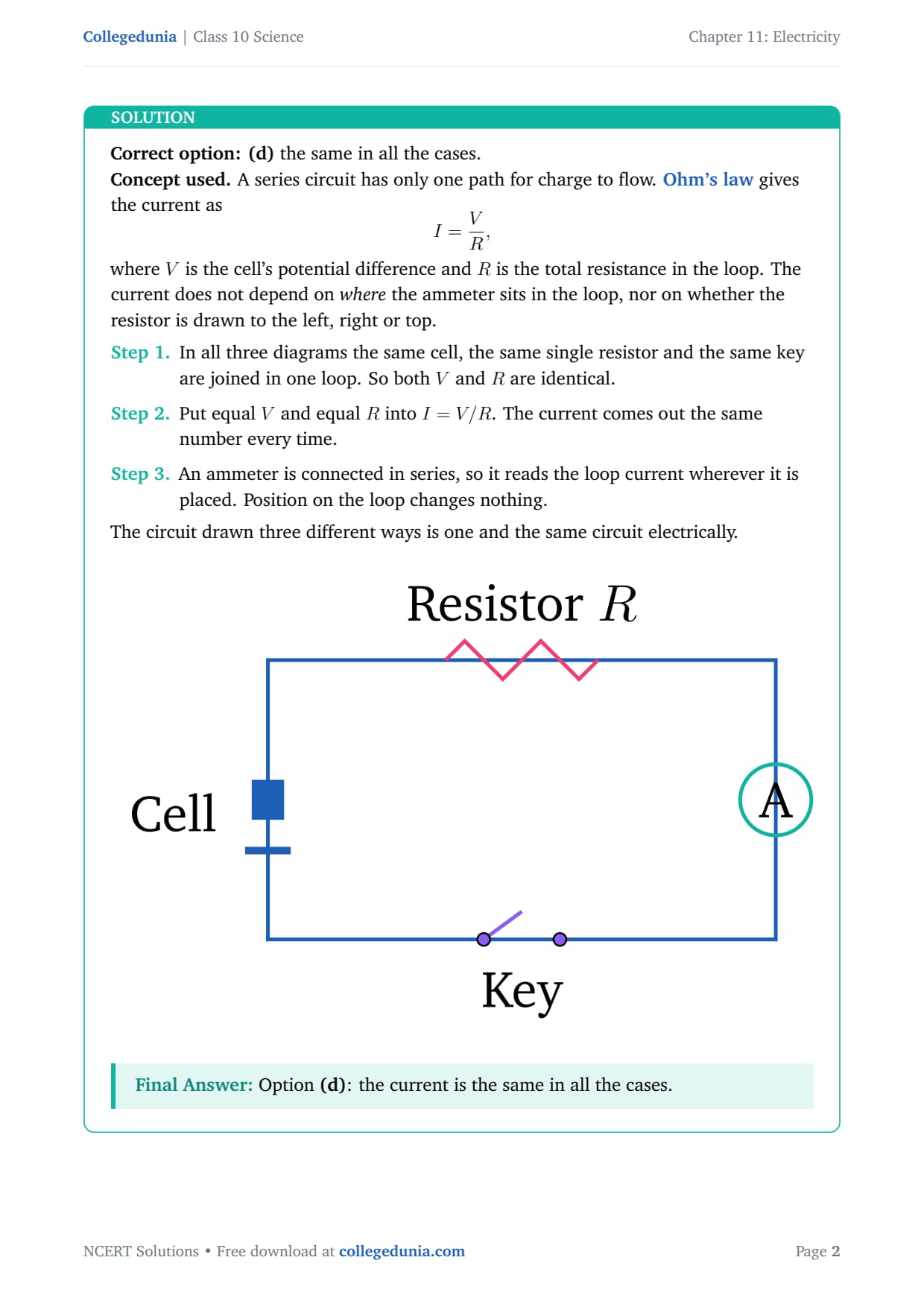
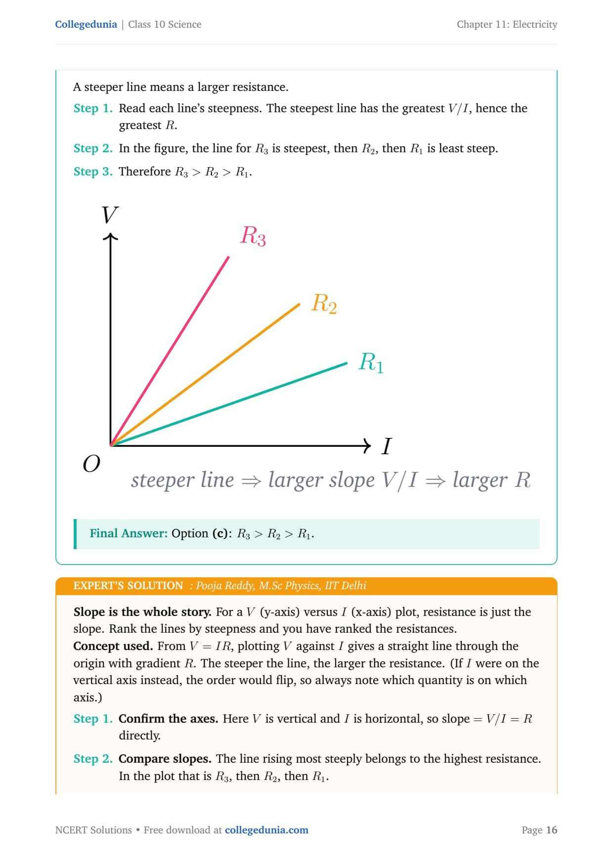
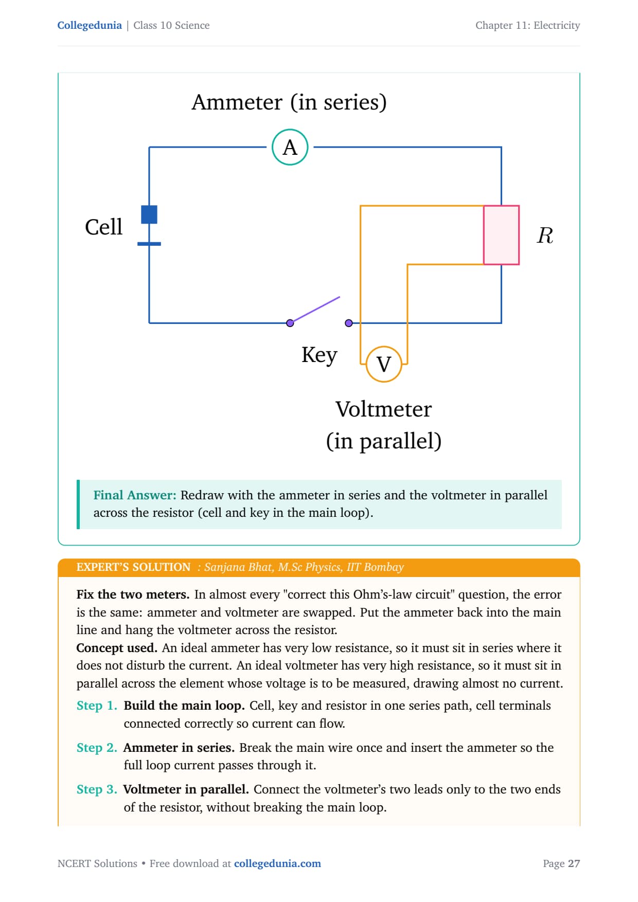
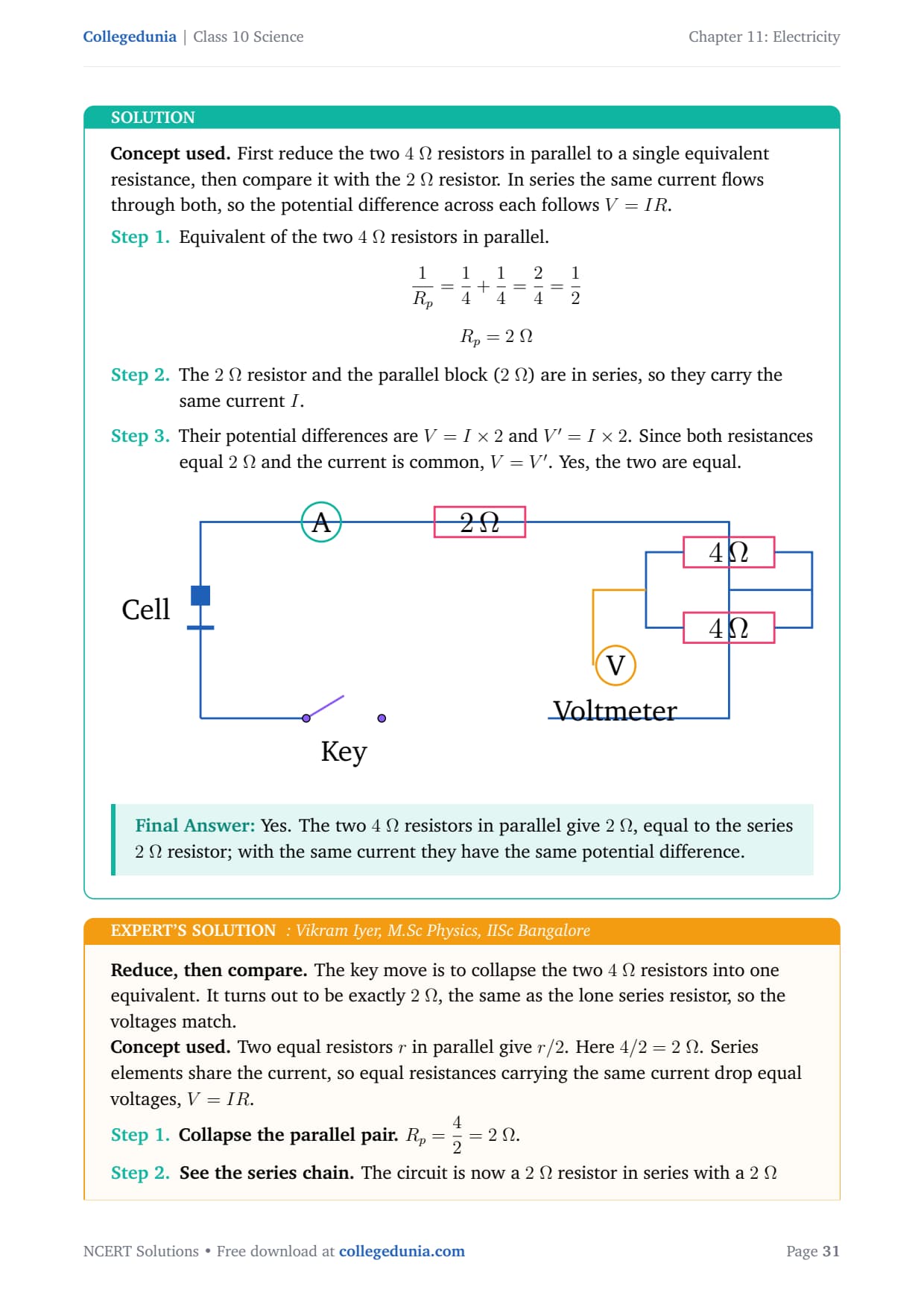
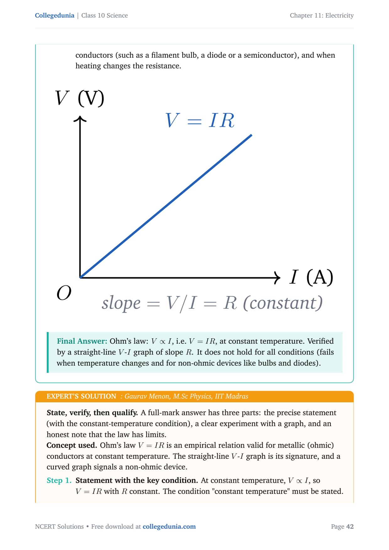
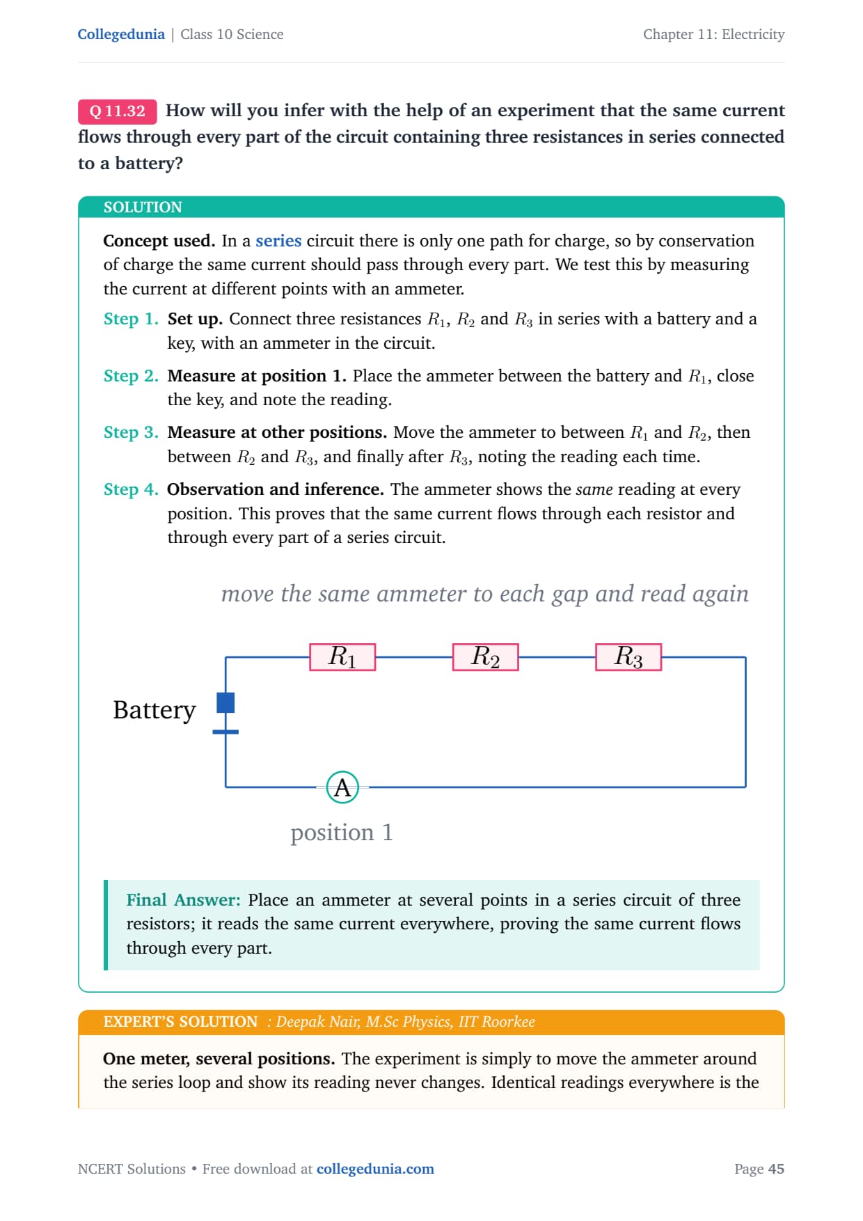
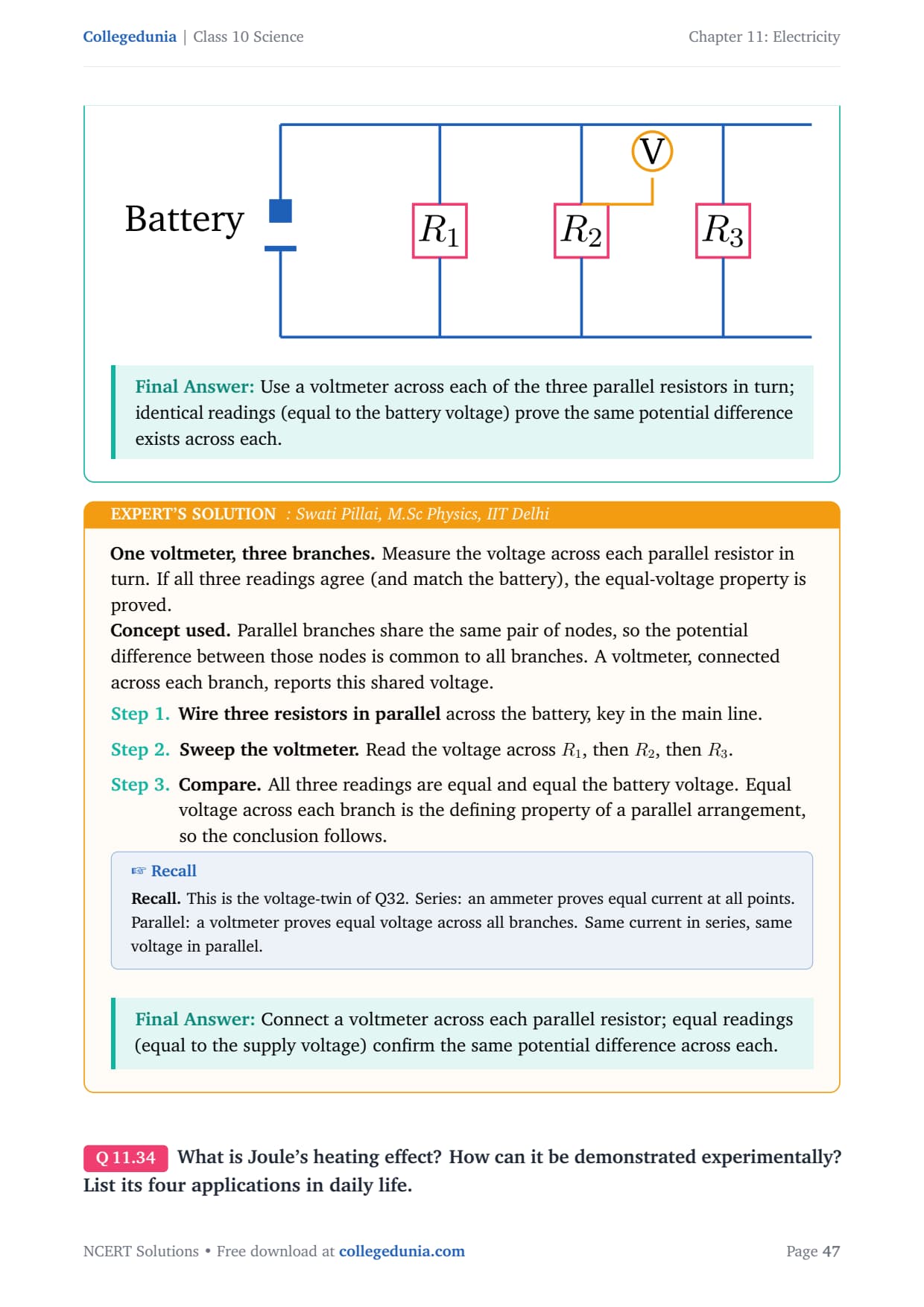




Comments