



Class 11 Engineering Graphics Chapter 2 Lines, Angles, and Rectilinear Figures NCERT Solutions help students revise the 2026-27 NCERT drawing rules with solved answers. The PDF covers line types, angle names, CAD, lettering, drawing instruments and dimensioning in simple steps.
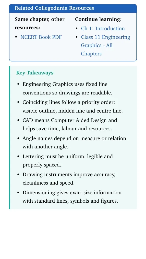
- Includes 12 solved answers from the assignment and test-yourself sections.
- Covers line conventions, angle types, lettering rules, instruments and dimensioning.
- Useful before drawing sheets, plane-geometry practice and technical lettering work.
Student Feedback: In a Collegedunia poll of 11,420 Class 11 Engineering Graphics students conducted before the 2026 boards, 74% said this chapter became easier after they memorised line types first.
Use this with the official 2026-27 NCERT chapter. Read the drawing convention first, then write the answer in the same order.
Lines, Angles, and Rectilinear Figures Solution Highlights
This chapter builds the base for technical drawing. Line type is the first scoring point because a visible outline, centre line and dimension line cannot be drawn in the same way. The solved PDF keeps every answer short enough for notebook writing.
| NCERT focus | What students should remember |
|---|---|
| Types of lines | Continuous thick, thin continuous, hidden, centre, break and hatching lines. |
| Angles | Acute, right, obtuse, straight, reflex, adjacent, complementary and supplementary angles. |
| Lettering | Single stroke Gothic letters need uniform height, width, stroke and spacing. |
| Dimensioning | Dimension lines, extension lines, leader lines, arrowheads and symbols show size. |
Engineering Graphics Line Types Every Student Must Know
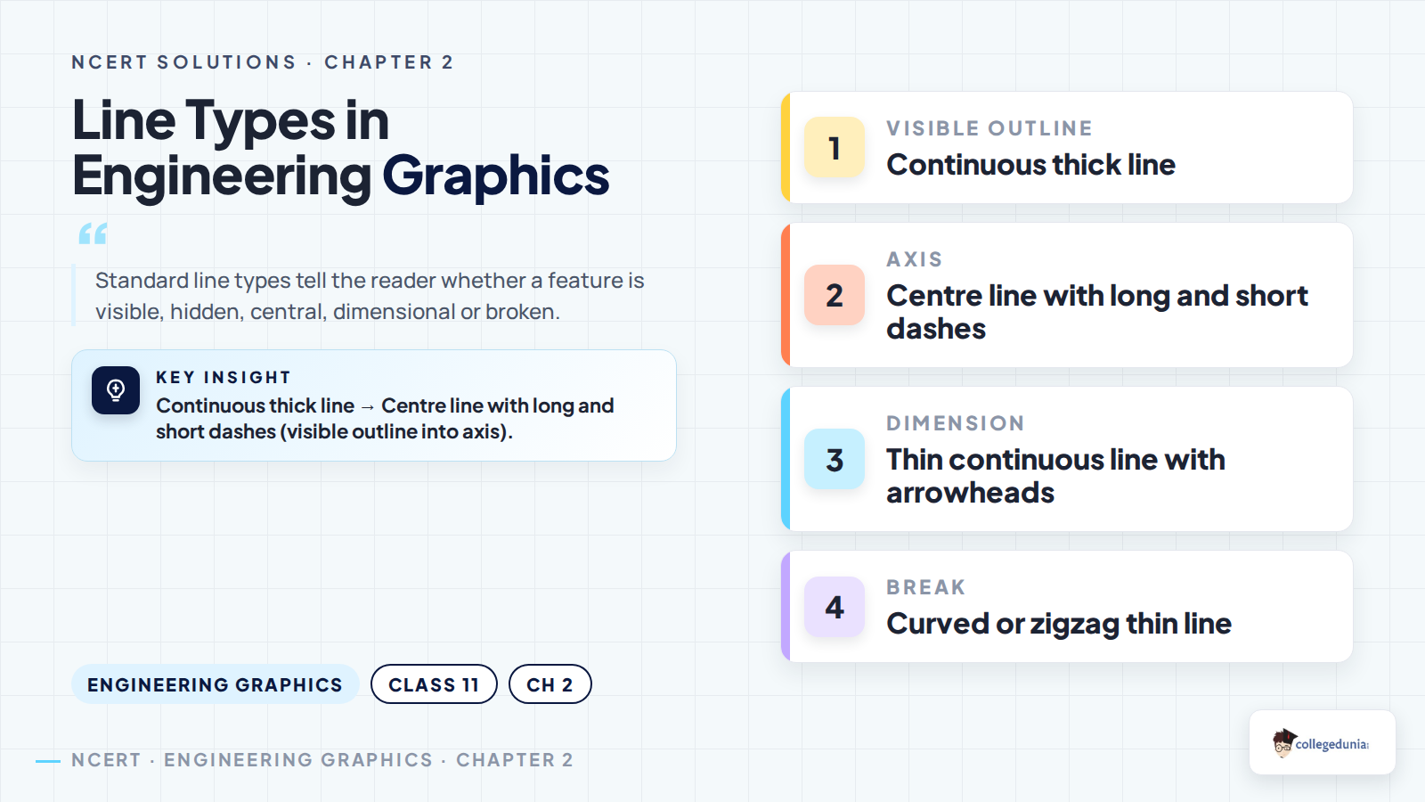
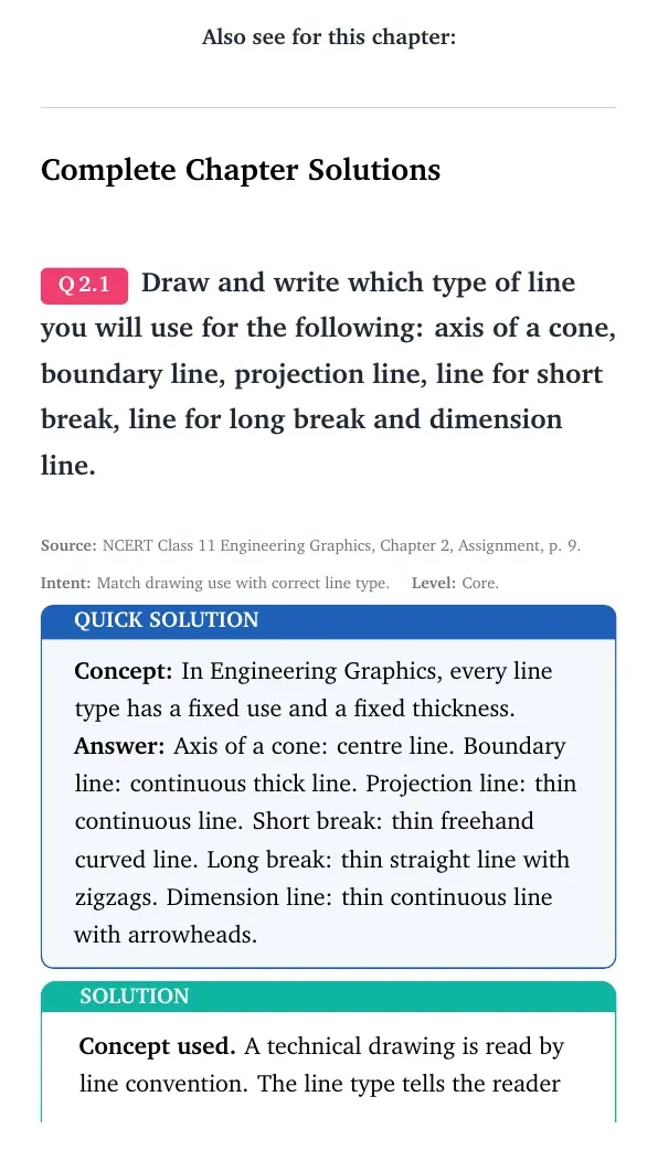
Engineering Graphics uses standard line conventions so a drawing can be read without extra explanation. A continuous thick line shows the visible boundary. A centre line marks an axis. Projection and dimension lines stay thin so they do not overpower the object.
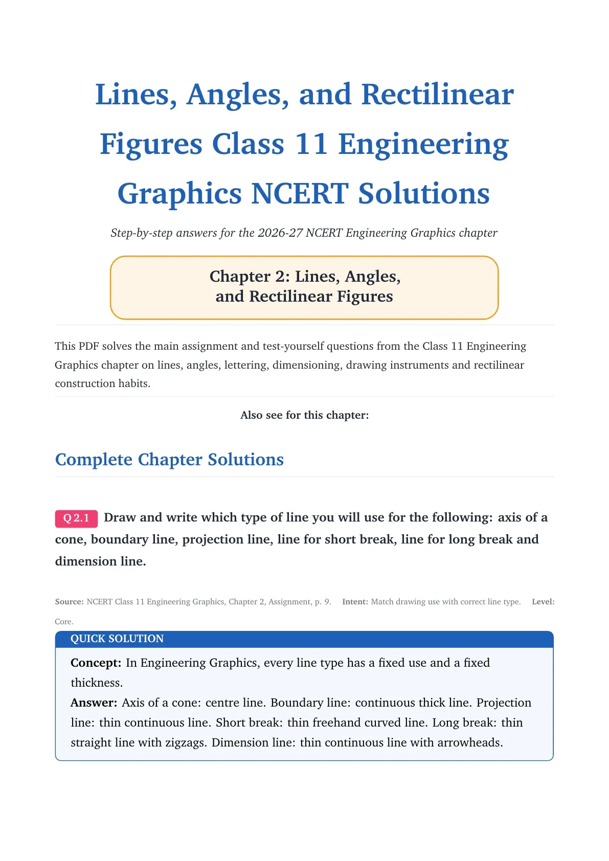
- Axis of cone: centre line with long and short dashes.
- Boundary line: continuous thick line.
- Projection line: thin continuous line.
- Short break: thin freehand curved line.
- Long break: thin straight line with zigzags.
Lines and Rectilinear Figures Video for Class 11 Engineering Graphics
Source: VISHWAKARMA ENGINEERING DRAWING CLASSES on YouTube
Dimensioning and Lettering Rules in the Engineering Graphics Chapter
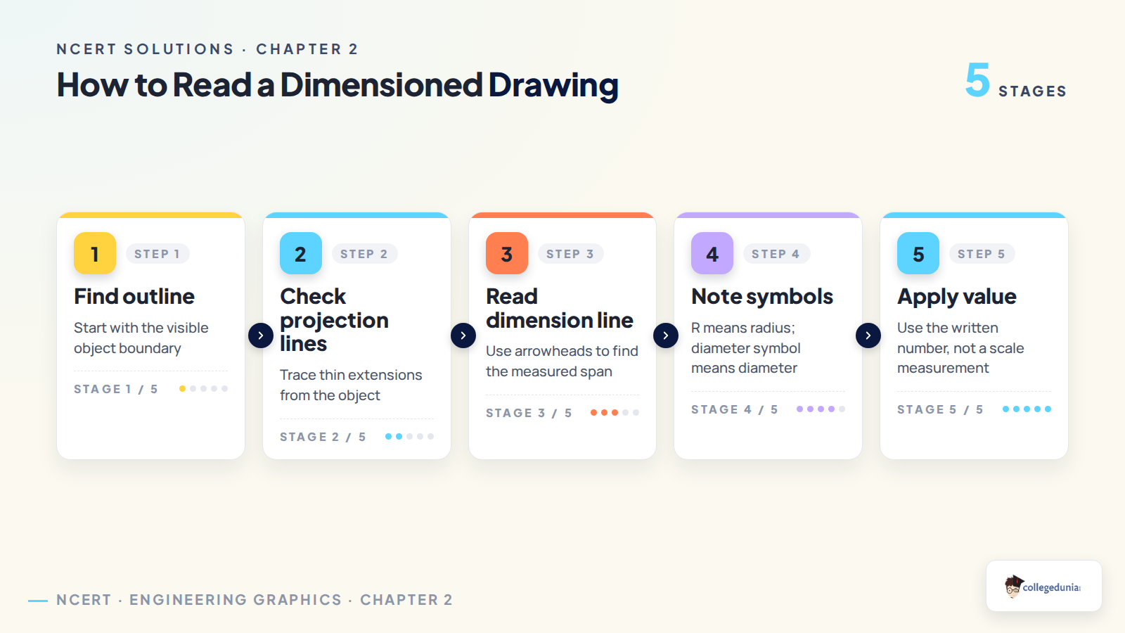
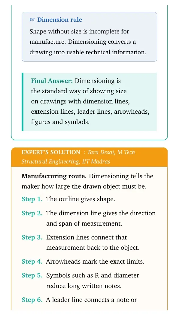
Dimensioning tells the maker the real size of an object. The drawing should not force students to guess from scale. The written dimension is the final size instruction, so arrowheads, extension lines and symbols must be clear.
- Use thin continuous dimension lines with arrowheads.
- Extend projection lines about 3 mm beyond the dimension line.
- Use R before a radius value and the diameter symbol before a diameter value.
- Keep lettering uniform, legible and written with steady single strokes.
What the Class 11 Engineering Graphics Chapter 2 PDF Contains
The PDF solves the questions students usually need before sheet-work practice. It also gives a quick answer box before the detailed solution, so students can revise fast and then read the expert route.
| PDF section | Use |
|---|---|
| Quick Solution | Fast answer for revision before classwork. |
| Solution | Step-by-step explanation with the concept used. |
| Expert Solution | Cleaner writing route for exam-style answers. |
| Key Takeaways | Final list of rules to remember from the chapter. |
Related Lines, Angles, and Rectilinear Figures Class 11 Resources
Use these resources together. The official book PDF gives the source chapter, while the solutions PDF gives answer-ready points for the assignment and test-yourself questions.
| Resource | Best use | Link |
|---|---|---|
| NCERT Book PDF | Read the official chapter pages | Open book PDF |
| Revision Notes | Revise line types, lettering and dimensioning | Open notes |
| Handwritten Notes | Use a topper's handwritten revision notes | Open handwritten notes |
All Class 11 Engineering Graphics NCERT Solutions
The table below keeps the Engineering Graphics solution pages together for chapter-wise practice.
| Chapter | NCERT chapter title | Solutions |
|---|---|---|
| Chapter 1 | Introduction | Open solutions |
| Chapter 2 | Lines, Angles, and Rectilinear Figures | Current solutions |
| Chapter 3 | Circles, Inscribing and Circumscribing of Circles | Open solutions |
| Chapter 4 | Orthographic Projection of Points and Lines | Open solutions |
| Chapter 5 | Orthographic Projection of Regular Plane Figures | Open solutions |
| Chapter 6 | Orthographic Projection of Right Regular Solids | Open solutions |
| Chapter 7 | Section of Solids | Open solutions |
All NCERT Solutions for Class 11 Engineering Graphics Chapter 2 Lines, Angles, and Rectilinear Figures with Step-by-Step Solutions
The question cards below let students open each answer only when they need it. Start with the quick statement, then check the full solution and expert explanation.
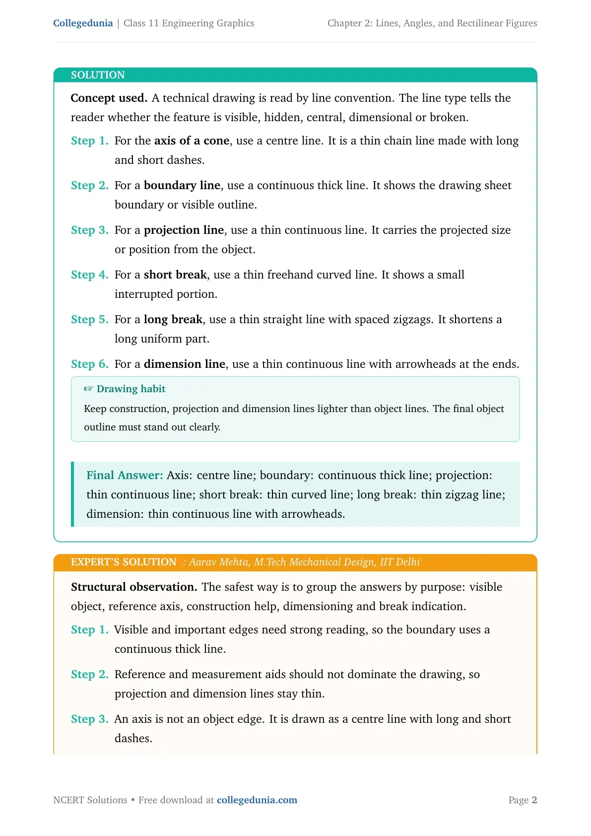
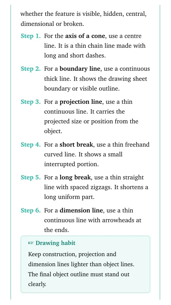
Concept used. A technical drawing is read by line convention. The line type tells the reader whether the feature is visible, hidden, central, dimensional or broken.
- For the axis of a cone, use a centre line. It is a thin chain line made with long and short dashes.
- For a boundary line, use a continuous thick line. It shows the drawing sheet boundary or visible outline.
- For a projection line, use a thin continuous line. It carries the projected size or position from the object.
- For a short break, use a thin freehand curved line. It shows a small interrupted portion.
- For a long break, use a thin straight line with spaced zigzags. It shortens a long uniform part.
- For a dimension line, use a thin continuous line with arrowheads at the ends.
Expert's Solution
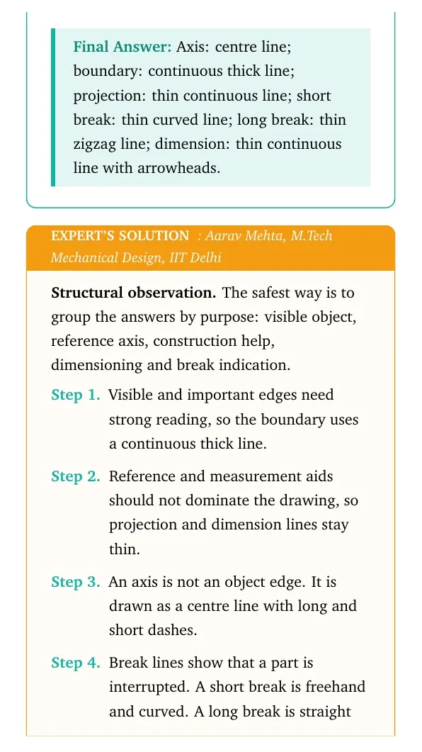
Structural observation. The safest way is to group the answers by purpose: visible object, reference axis, construction help, dimensioning and break indication.
- Visible and important edges need strong reading, so the boundary uses a continuous thick line.
- Reference and measurement aids should not dominate the drawing, so projection and dimension lines stay thin.
- An axis is not an object edge. It is drawn as a centre line with long and short dashes.
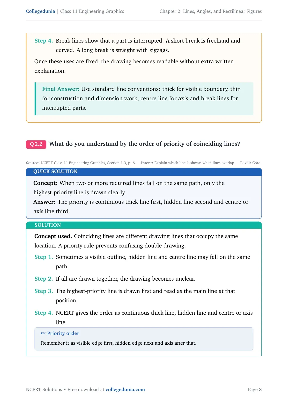
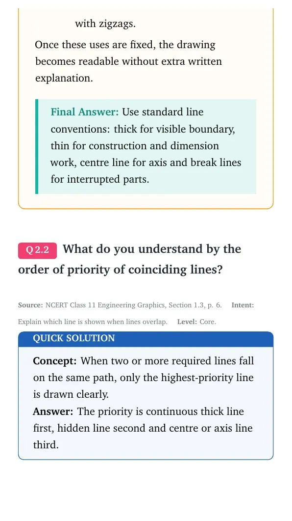
- Break lines show that a part is interrupted. A short break is freehand and curved. A long break is straight with zigzags.
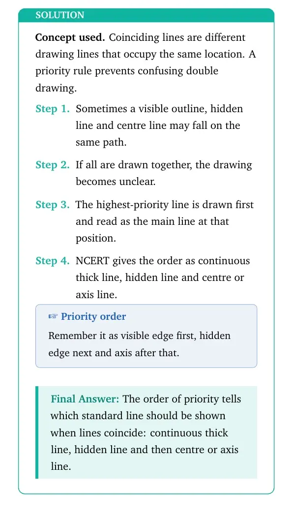
Concept used. Coinciding lines are different drawing lines that occupy the same location. A priority rule prevents confusing double drawing.
- Sometimes a visible outline, hidden line and centre line may fall on the same path.
- If all are drawn together, the drawing becomes unclear.
- The highest-priority line is drawn first and read as the main line at that position.
- NCERT gives the order as continuous thick line, hidden line and centre or axis line.
Expert's Solution
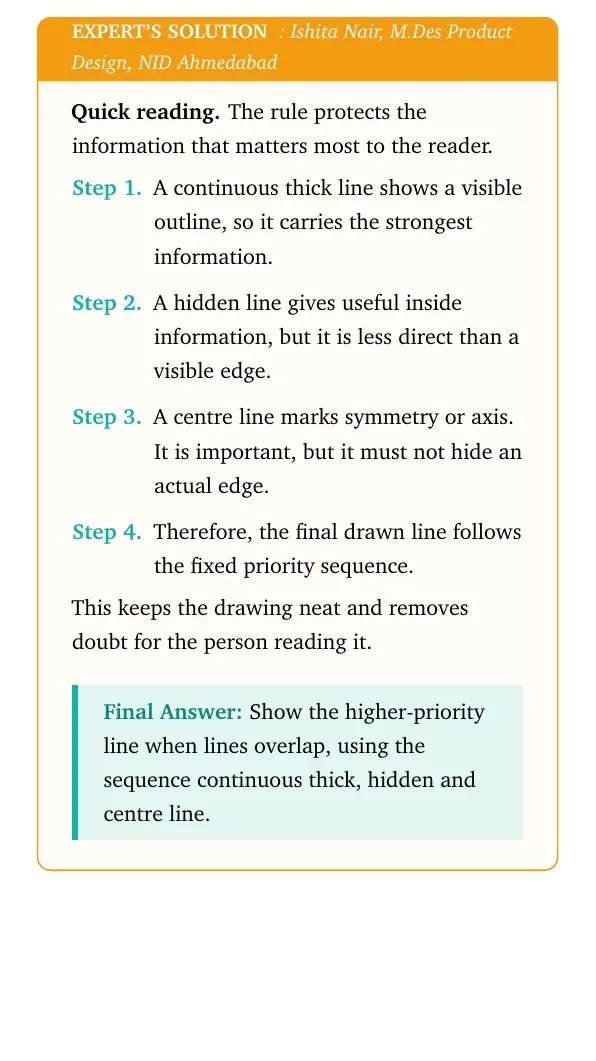
Quick reading. The rule protects the information that matters most to the reader.
- A continuous thick line shows a visible outline, so it carries the strongest information.
- A hidden line gives useful inside information, but it is less direct than a visible edge.
- A centre line marks symmetry or axis. It is important, but it must not hide an actual edge.
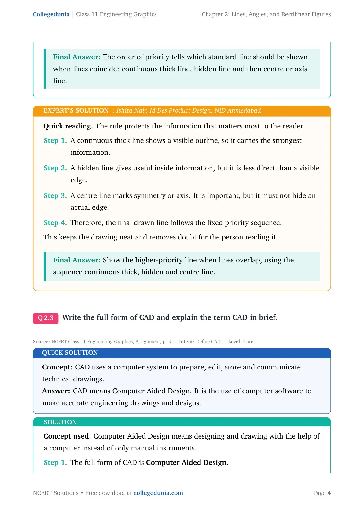
- Therefore, the final drawn line follows the fixed priority sequence.
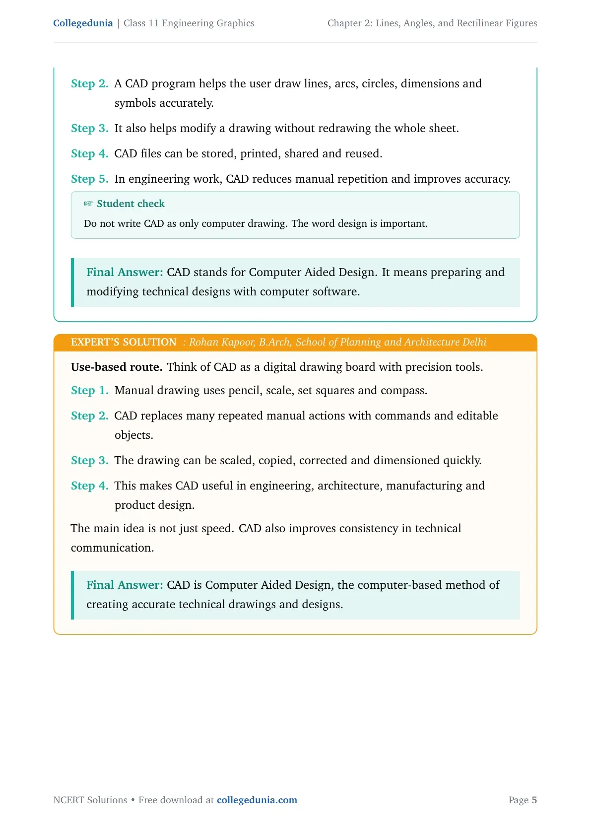
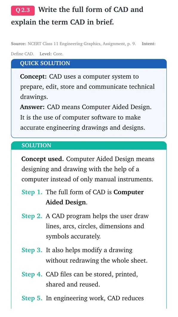
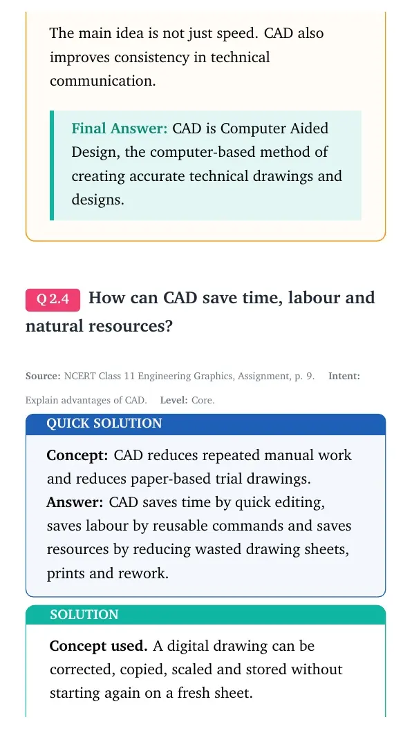
Concept used. Computer Aided Design means designing and drawing with the help of a computer instead of only manual instruments.
- The full form of CAD is Computer Aided Design.
- A CAD program helps the user draw lines, arcs, circles, dimensions and symbols accurately.
- It also helps modify a drawing without redrawing the whole sheet.
- CAD files can be stored, printed, shared and reused.
- In engineering work, CAD reduces manual repetition and improves accuracy.
Expert's Solution
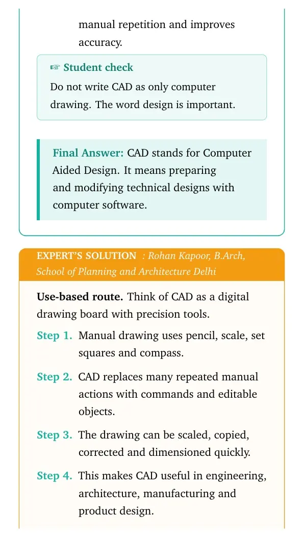
Use-based route. Think of CAD as a digital drawing board with precision tools.
- Manual drawing uses pencil, scale, set squares and compass.
- CAD replaces many repeated manual actions with commands and editable objects.
- The drawing can be scaled, copied, corrected and dimensioned quickly.
- This makes CAD useful in engineering, architecture, manufacturing and product design.
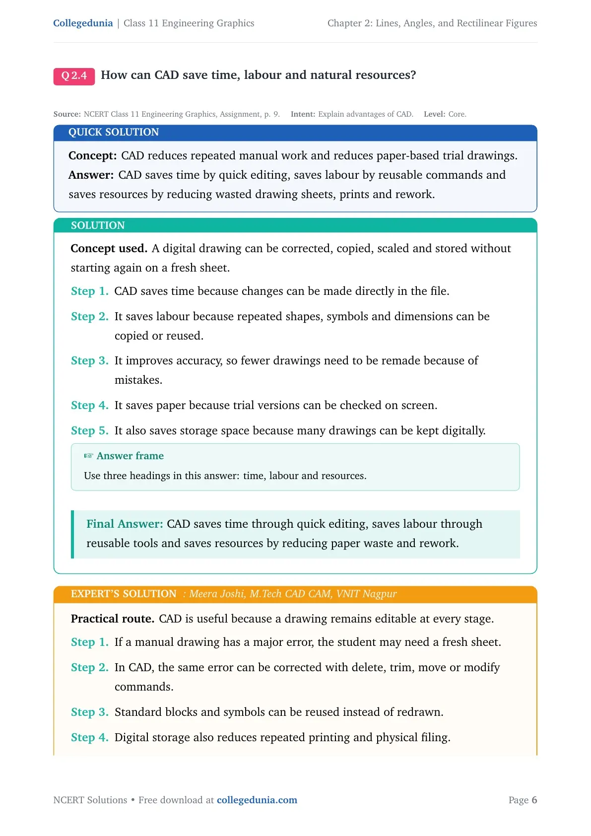
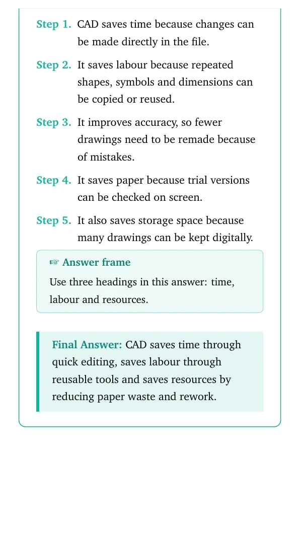
Concept used. A digital drawing can be corrected, copied, scaled and stored without starting again on a fresh sheet.
- CAD saves time because changes can be made directly in the file.
- It saves labour because repeated shapes, symbols and dimensions can be copied or reused.
- It improves accuracy, so fewer drawings need to be remade because of mistakes.
- It saves paper because trial versions can be checked on screen.
- It also saves storage space because many drawings can be kept digitally.
Expert's Solution
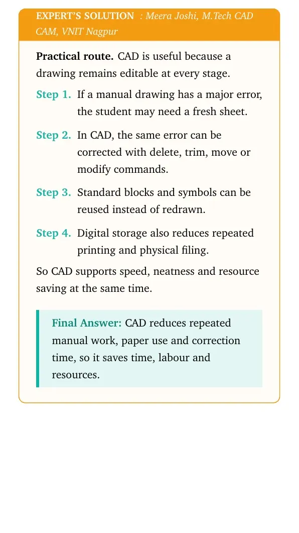
Practical route. CAD is useful because a drawing remains editable at every stage.
- If a manual drawing has a major error, the student may need a fresh sheet.
- In CAD, the same error can be corrected with delete, trim, move or modify commands.
- Standard blocks and symbols can be reused instead of redrawn.
- Digital storage also reduces repeated printing and physical filing.
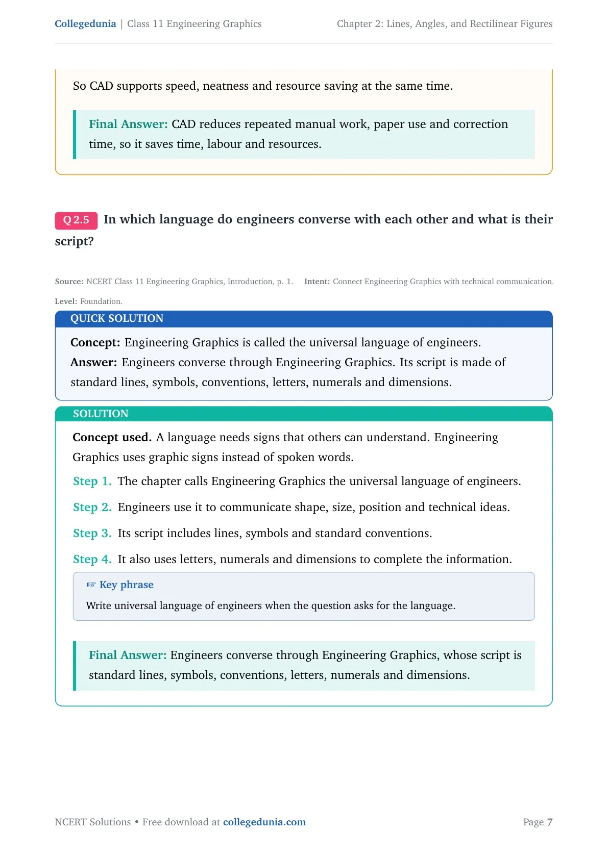
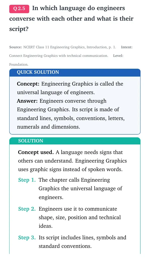
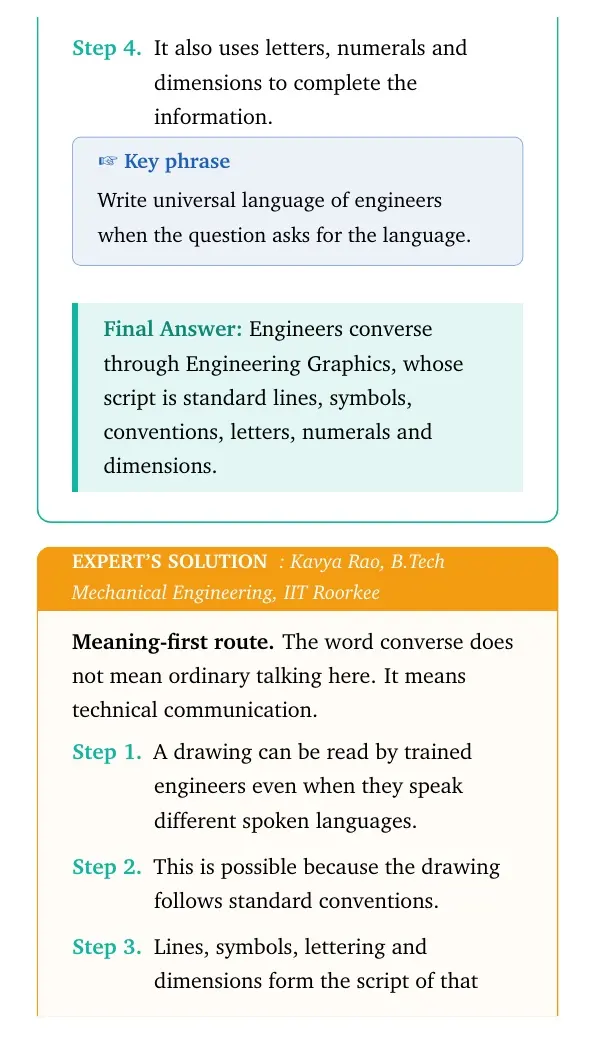
Concept used. A language needs signs that others can understand. Engineering Graphics uses graphic signs instead of spoken words.
- The chapter calls Engineering Graphics the universal language of engineers.
- Engineers use it to communicate shape, size, position and technical ideas.
- Its script includes lines, symbols and standard conventions.
- It also uses letters, numerals and dimensions to complete the information.
Expert's Solution
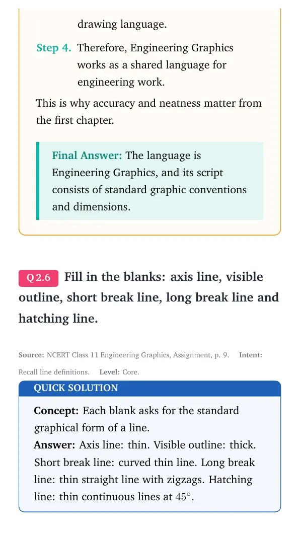
Meaning-first route. The word converse does not mean ordinary talking here. It means technical communication.
- A drawing can be read by trained engineers even when they speak different spoken languages.
- This is possible because the drawing follows standard conventions.
- Lines, symbols, lettering and dimensions form the script of that drawing language.
- Therefore, Engineering Graphics works as a shared language for engineering work.
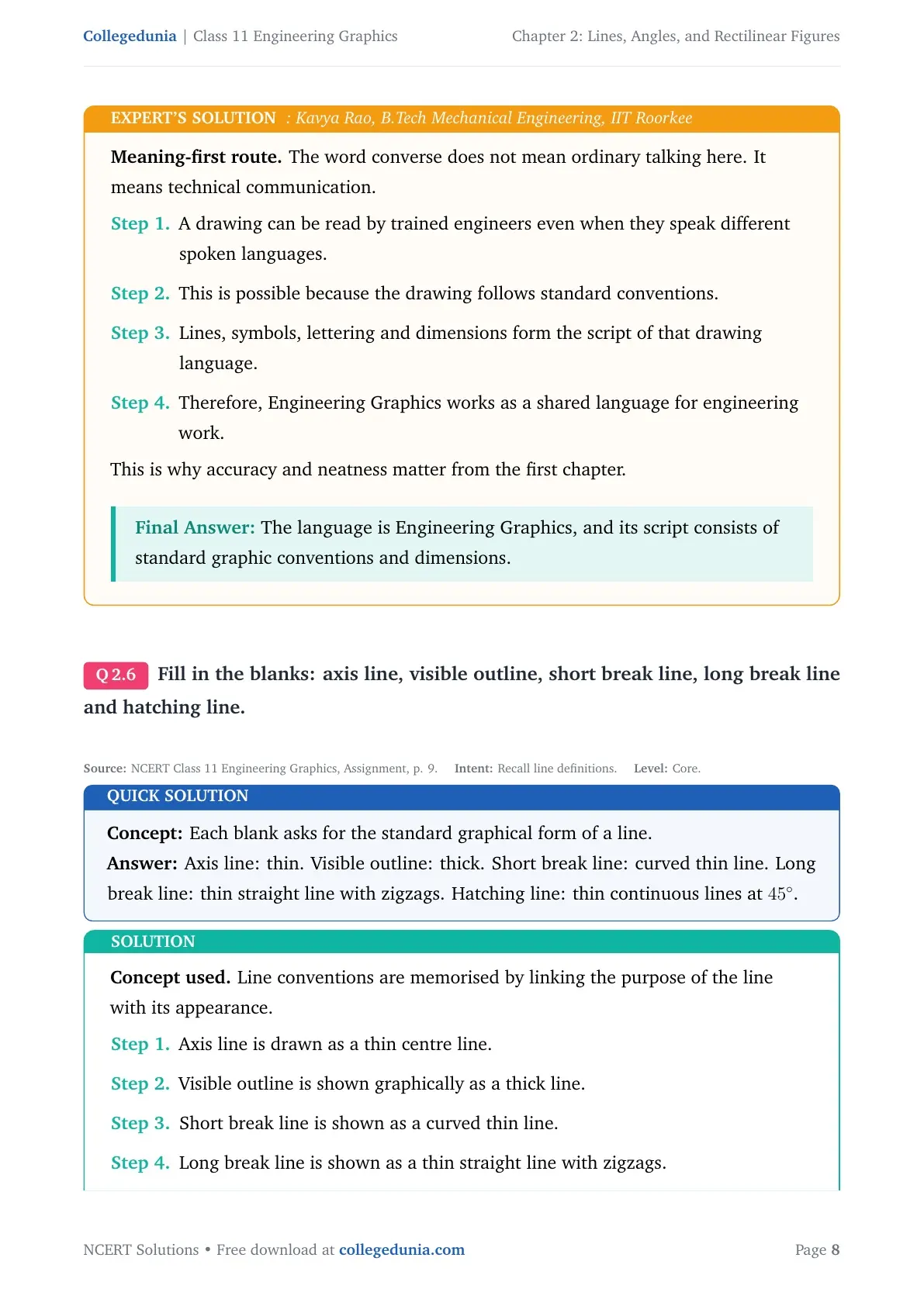
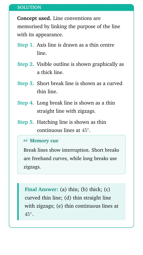
Concept used. Line conventions are memorised by linking the purpose of the line with its appearance.
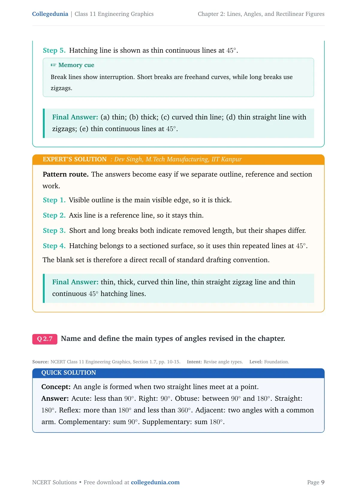
- Axis line is drawn as a thin centre line.
- Visible outline is shown graphically as a thick line.
- Short break line is shown as a curved thin line.
- Long break line is shown as a thin straight line with zigzags.
- Hatching line is shown as thin continuous lines at 45∘.
Expert's Solution
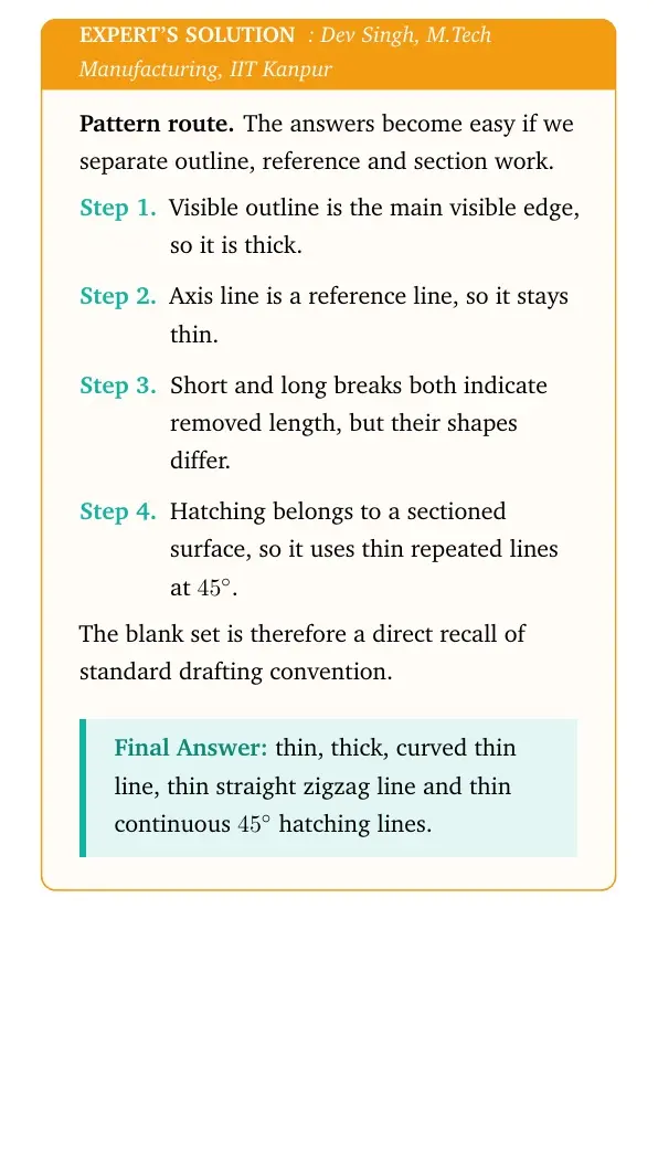
Pattern route. The answers become easy if we separate outline, reference and section work.
- Visible outline is the main visible edge, so it is thick.
- Axis line is a reference line, so it stays thin.
- Short and long breaks both indicate removed length, but their shapes differ.
- Hatching belongs to a sectioned surface, so it uses thin repeated lines at 45∘.
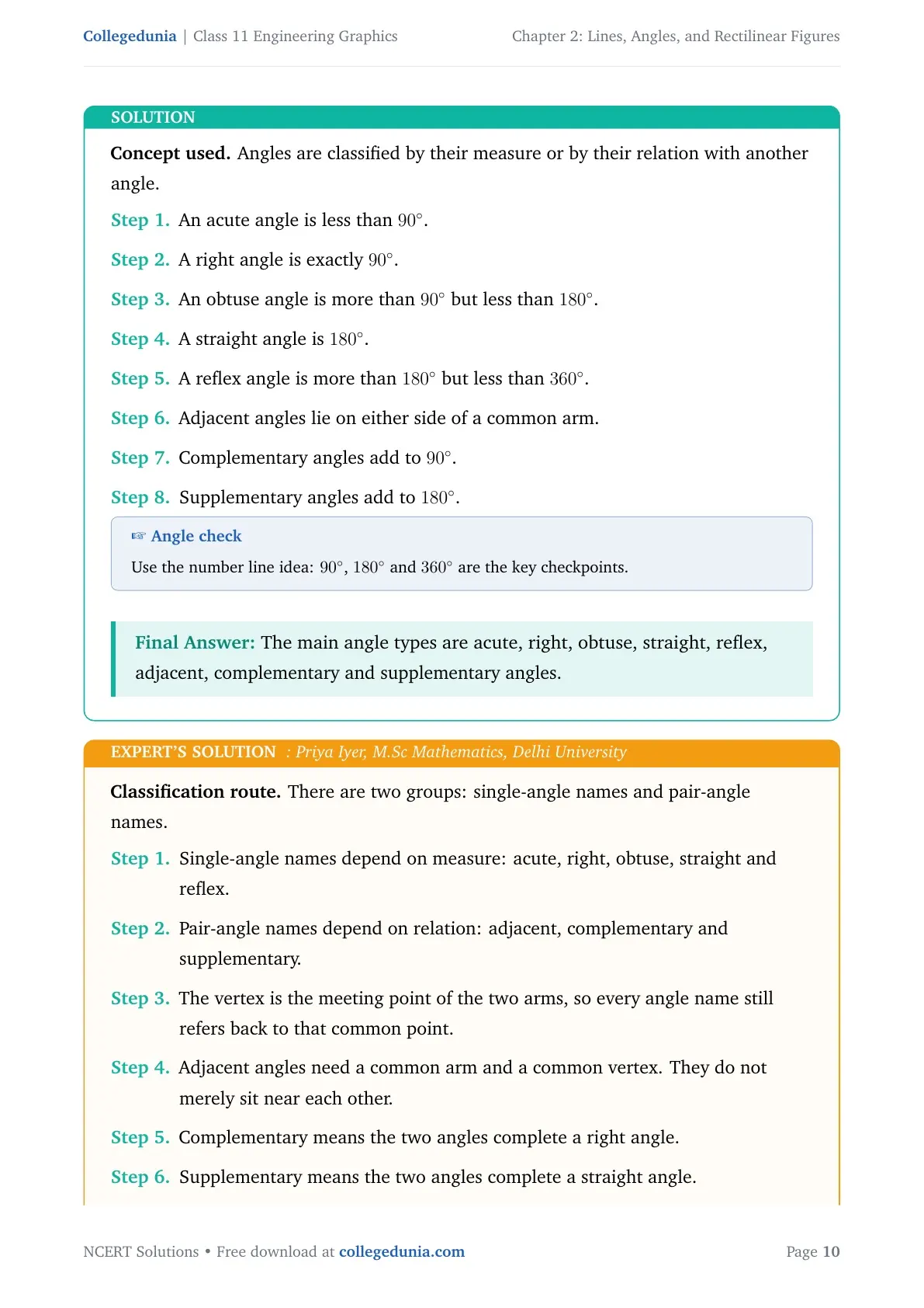
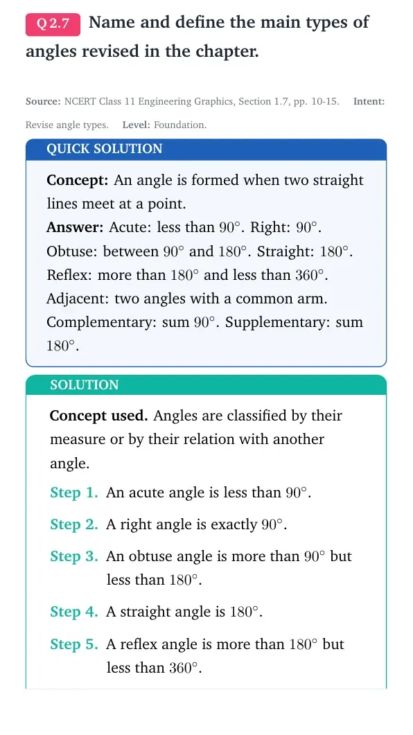
Concept used. Angles are classified by their measure or by their relation with another angle.
- An acute angle is less than 90∘.
- A right angle is exactly 90∘.
- An obtuse angle is more than 90∘ but less than 180∘.
- A straight angle is 180∘.
- A reflex angle is more than 180∘ but less than 360∘.
- Adjacent angles lie on either side of a common arm.
- Complementary angles add to 90∘.
- Supplementary angles add to 180∘.
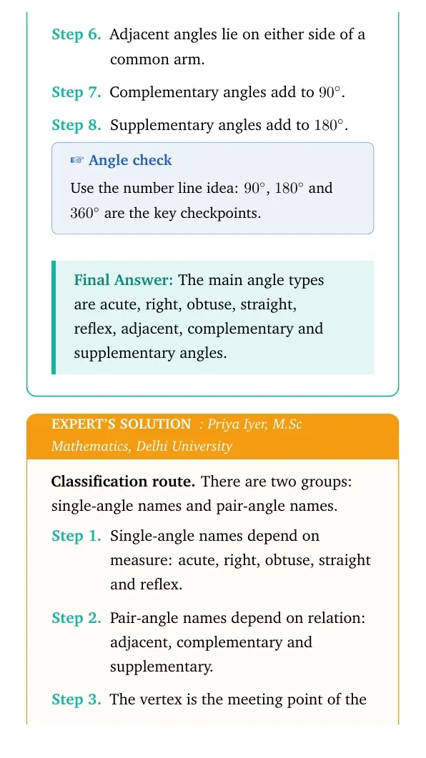
Expert's Solution
Classification route. There are two groups: single-angle names and pair-angle names.
- Single-angle names depend on measure: acute, right, obtuse, straight and reflex.
- Pair-angle names depend on relation: adjacent, complementary and supplementary.
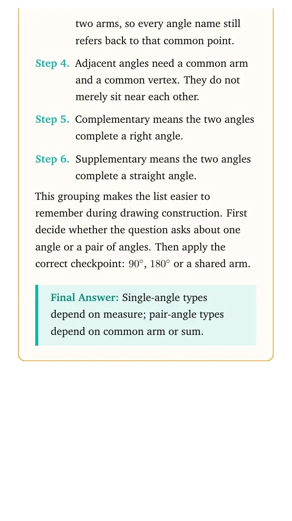
- The vertex is the meeting point of the two arms, so every angle name still refers back to that common point.
- Adjacent angles need a common arm and a common vertex. They do not merely sit near each other.
- Complementary means the two angles complete a right angle.
- Supplementary means the two angles complete a straight angle.
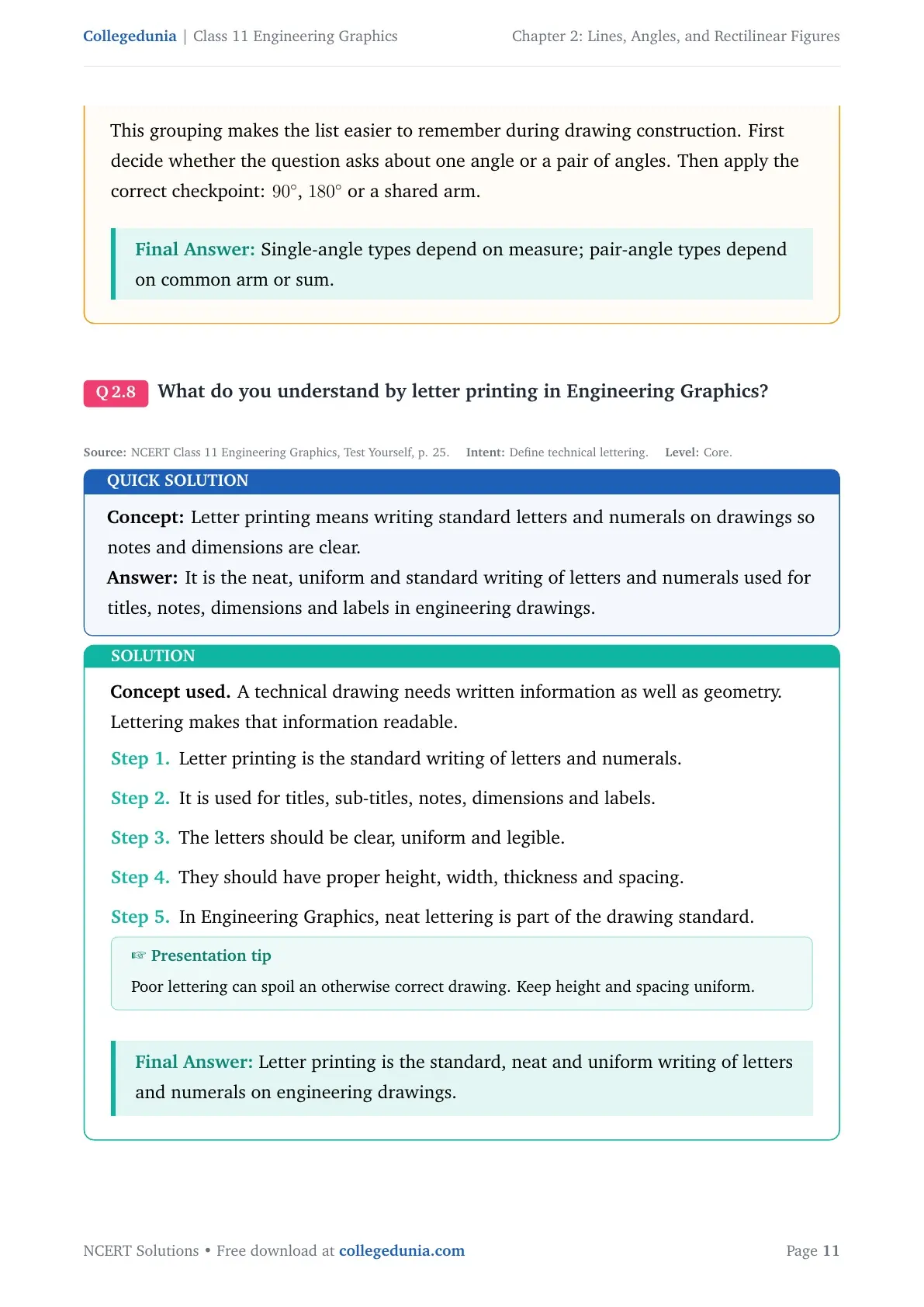
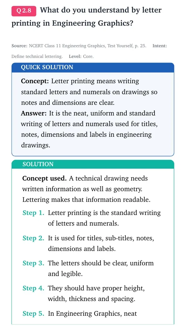
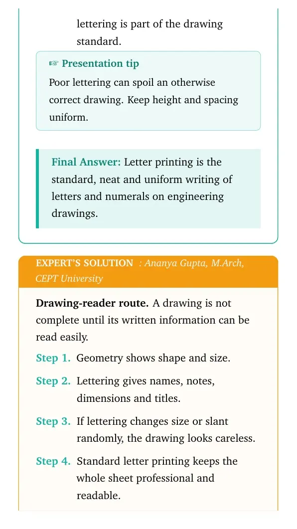
Concept used. A technical drawing needs written information as well as geometry. Lettering makes that information readable.
- Letter printing is the standard writing of letters and numerals.
- It is used for titles, sub-titles, notes, dimensions and labels.
- The letters should be clear, uniform and legible.
- They should have proper height, width, thickness and spacing.
- In Engineering Graphics, neat lettering is part of the drawing standard.
Expert's Solution
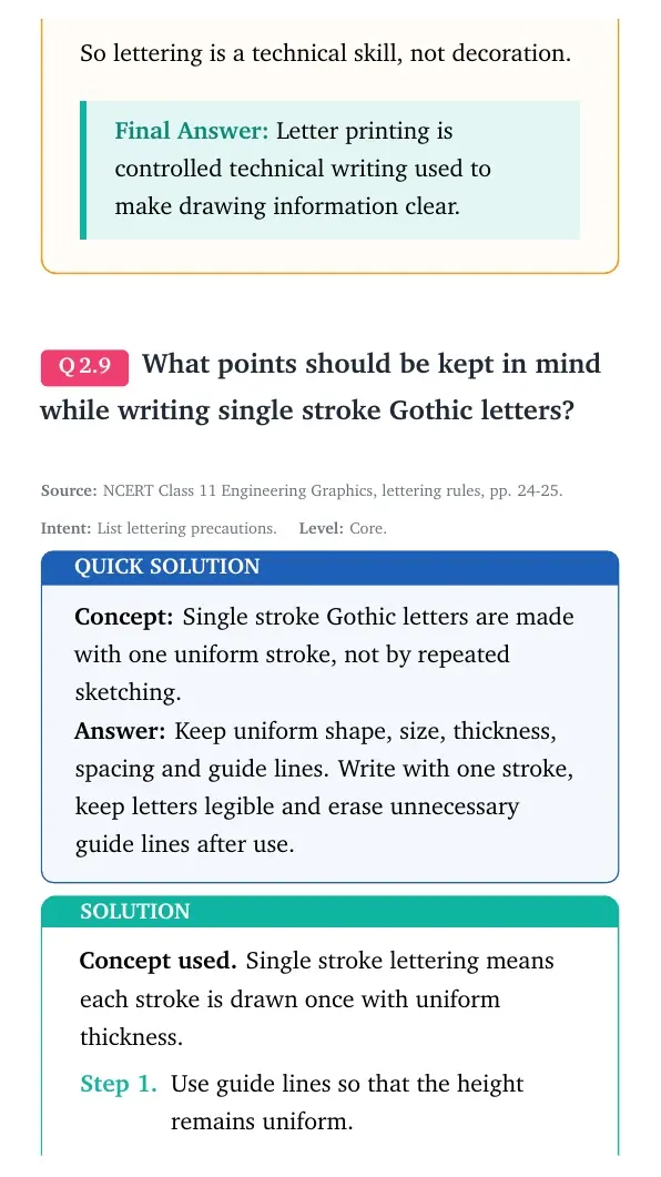
Drawing-reader route. A drawing is not complete until its written information can be read easily.
- Geometry shows shape and size.
- Lettering gives names, notes, dimensions and titles.
- If lettering changes size or slant randomly, the drawing looks careless.
- Standard letter printing keeps the whole sheet professional and readable.
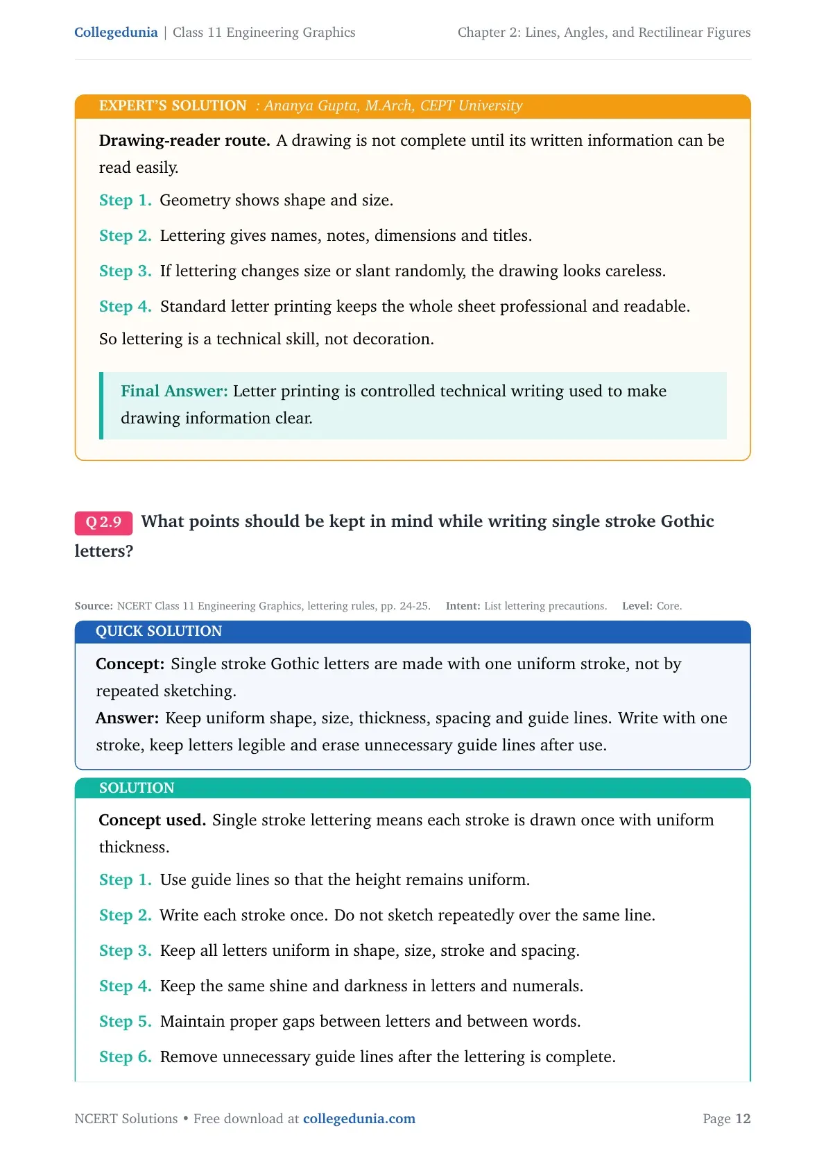
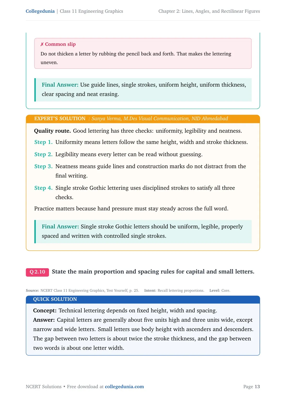
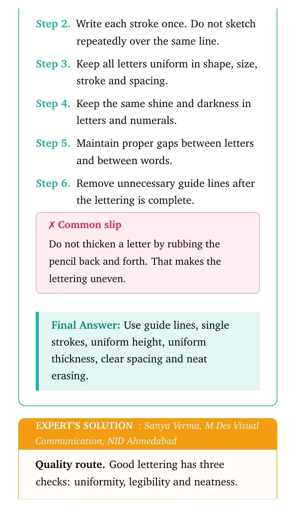
Concept used. Single stroke lettering means each stroke is drawn once with uniform thickness.
- Use guide lines so that the height remains uniform.
- Write each stroke once. Do not sketch repeatedly over the same line.
- Keep all letters uniform in shape, size, stroke and spacing.
- Keep the same shine and darkness in letters and numerals.
- Maintain proper gaps between letters and between words.
- Remove unnecessary guide lines after the lettering is complete.
Expert's Solution
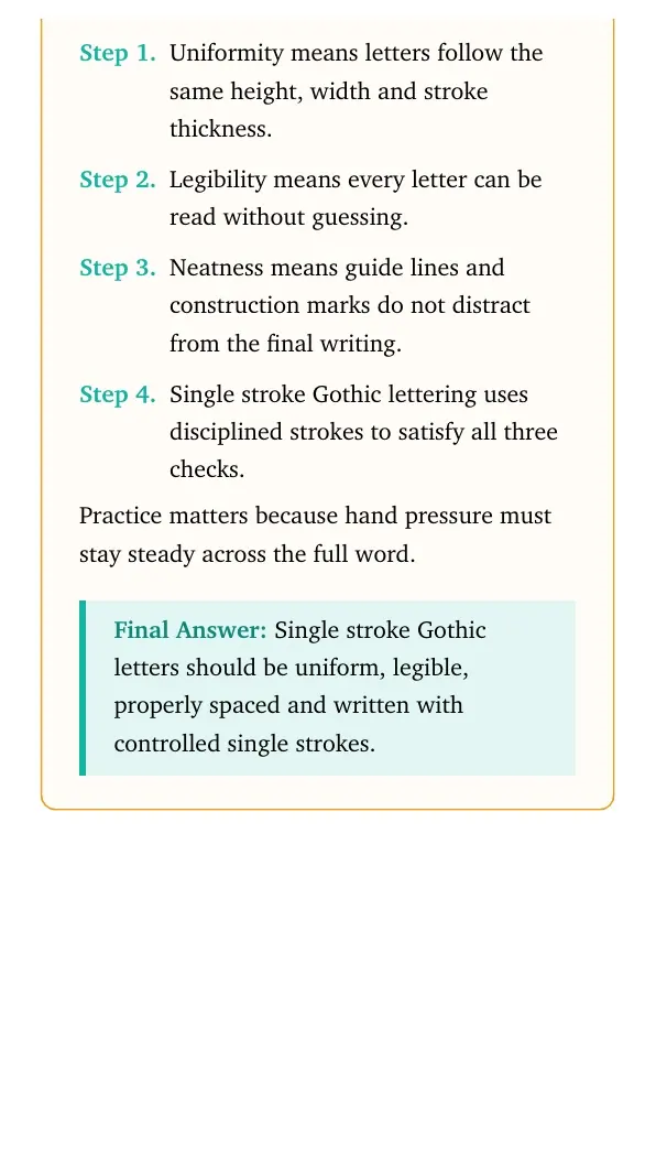
Quality route. Good lettering has three checks: uniformity, legibility and neatness.
- Uniformity means letters follow the same height, width and stroke thickness.
- Legibility means every letter can be read without guessing.
- Neatness means guide lines and construction marks do not distract from the final writing.
- Single stroke Gothic lettering uses disciplined strokes to satisfy all three checks.
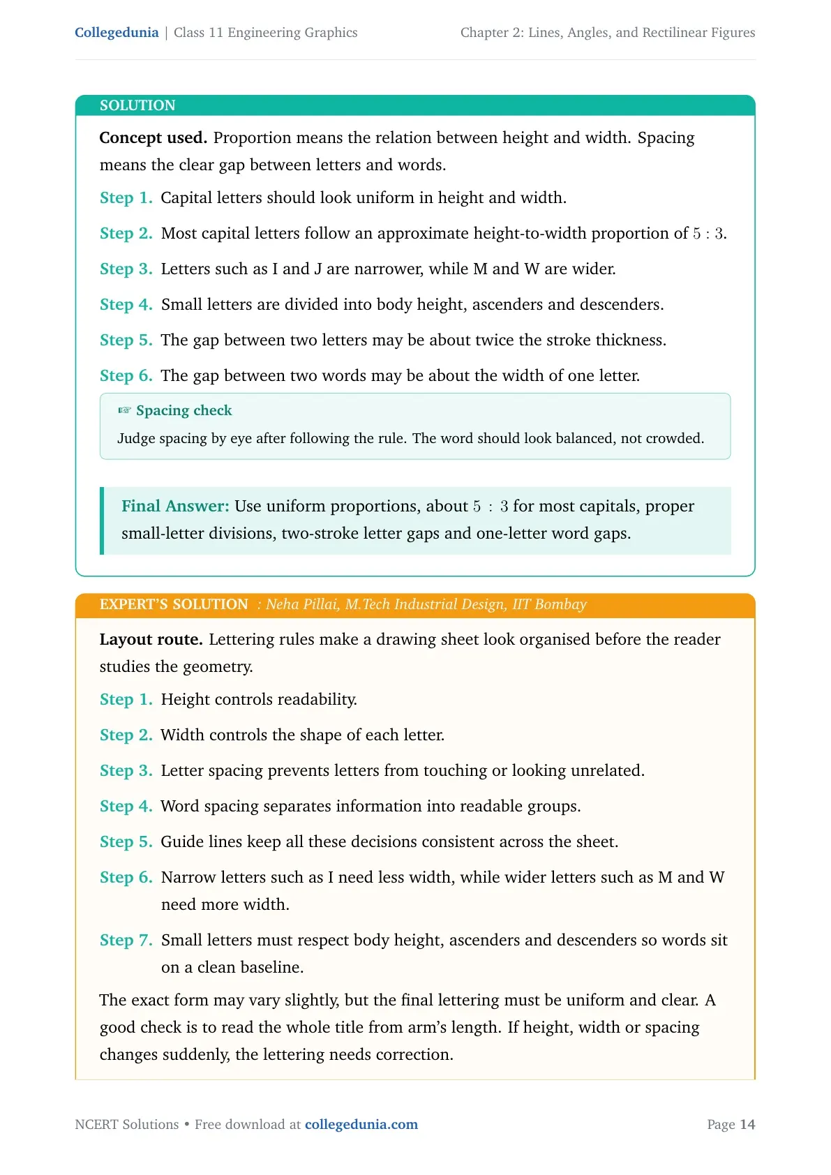
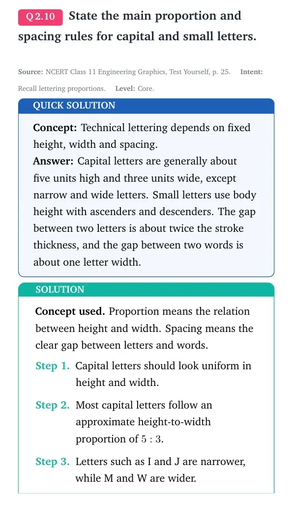
Concept used. Proportion means the relation between height and width. Spacing means the clear gap between letters and words.
- Capital letters should look uniform in height and width.
- Most capital letters follow an approximate height-to-width proportion of 5:3.
- Letters such as I and J are narrower, while M and W are wider.
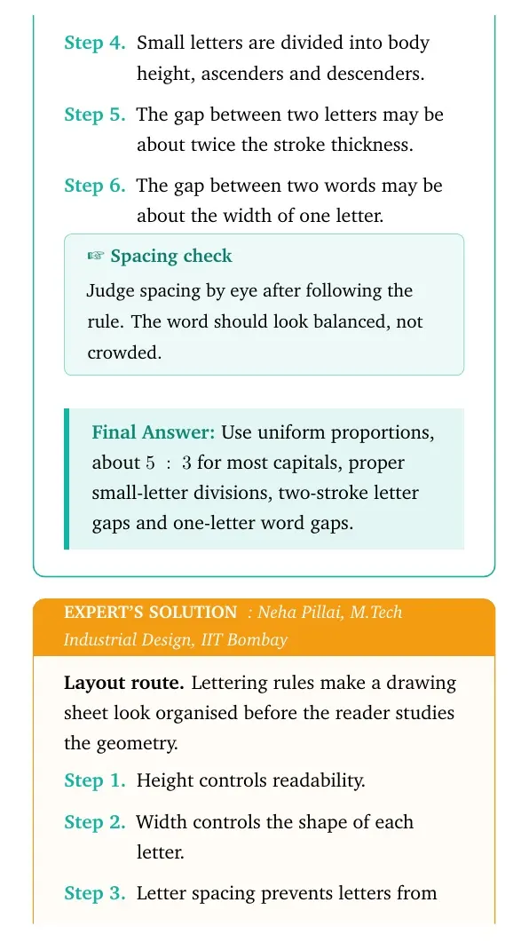
- Small letters are divided into body height, ascenders and descenders.
- The gap between two letters may be about twice the stroke thickness.
- The gap between two words may be about the width of one letter.
Expert's Solution
Layout route. Lettering rules make a drawing sheet look organised before the reader studies the geometry.
- Height controls readability.
- Width controls the shape of each letter.
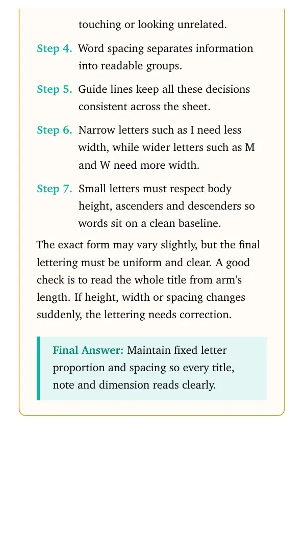
- Letter spacing prevents letters from touching or looking unrelated.
- Word spacing separates information into readable groups.
- Guide lines keep all these decisions consistent across the sheet.
- Narrow letters such as I need less width, while wider letters such as M and W need more width.
- Small letters must respect body height, ascenders and descenders so words sit on a clean baseline.
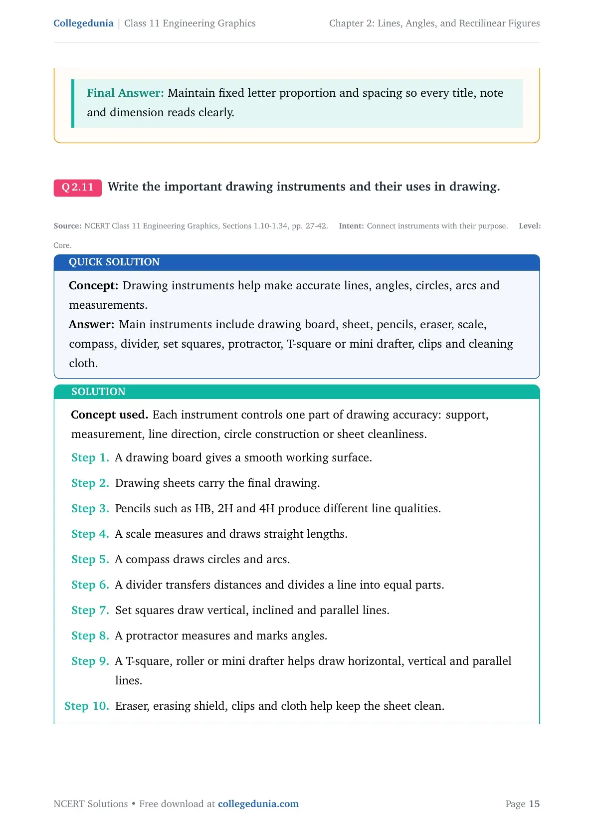
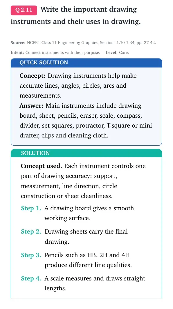
Concept used. Each instrument controls one part of drawing accuracy: support, measurement, line direction, circle construction or sheet cleanliness.
- A drawing board gives a smooth working surface.
- Drawing sheets carry the final drawing.
- Pencils such as HB, 2H and 4H produce different line qualities.
- A scale measures and draws straight lengths.
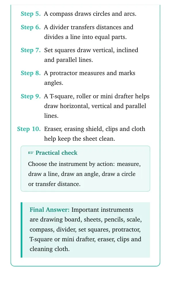
- A compass draws circles and arcs.
- A divider transfers distances and divides a line into equal parts.
- Set squares draw vertical, inclined and parallel lines.
- A protractor measures and marks angles.
- A T-square, roller or mini drafter helps draw horizontal, vertical and parallel lines.
- Eraser, erasing shield, clips and cloth help keep the sheet clean.
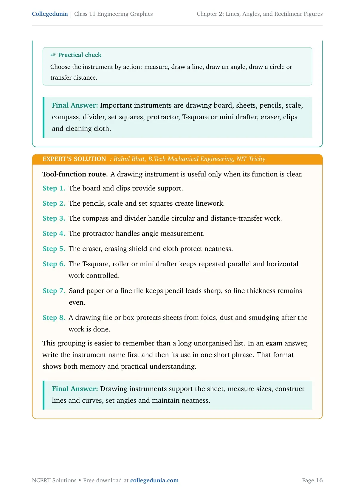
Expert's Solution
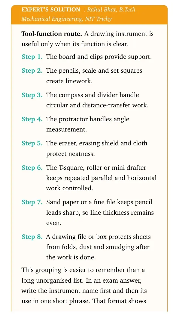
Tool-function route. A drawing instrument is useful only when its function is clear.
- The board and clips provide support.
- The pencils, scale and set squares create linework.
- The compass and divider handle circular and distance-transfer work.
- The protractor handles angle measurement.
- The eraser, erasing shield and cloth protect neatness.
- The T-square, roller or mini drafter keeps repeated parallel and horizontal work controlled.
- Sand paper or a fine file keeps pencil leads sharp, so line thickness remains even.
- A drawing file or box protects sheets from folds, dust and smudging after the work is done.
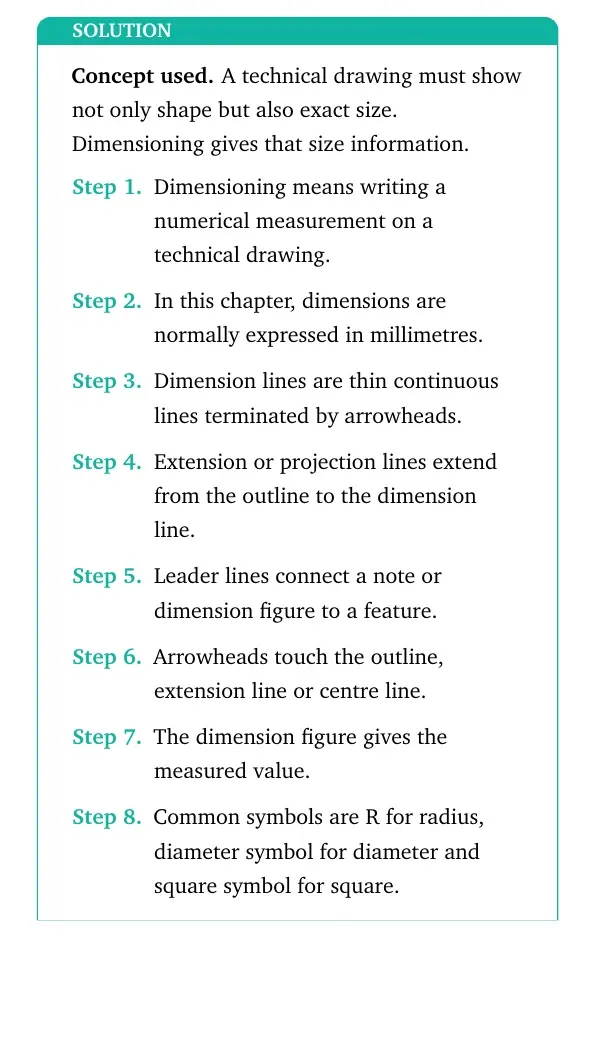
Concept used. A technical drawing must show not only shape but also exact size. Dimensioning gives that size information.
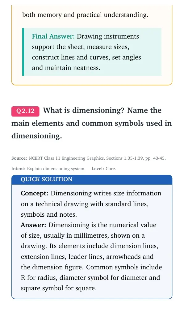
- Dimensioning means writing a numerical measurement on a technical drawing.
- In this chapter, dimensions are normally expressed in millimetres.
- Dimension lines are thin continuous lines terminated by arrowheads.
- Extension or projection lines extend from the outline to the dimension line.
- Leader lines connect a note or dimension figure to a feature.
- Arrowheads touch the outline, extension line or centre line.
- The dimension figure gives the measured value.
- Common symbols are R for radius, diameter symbol for diameter and square symbol for square.
Expert's Solution
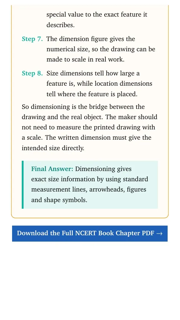
Manufacturing route. Dimensioning tells the maker how large the drawn object must be.
- The outline gives shape.
- The dimension line gives the direction and span of measurement.
- Extension lines connect that measurement back to the object.
- Arrowheads mark the exact limits.
- Symbols such as R and diameter reduce long written notes.
- A leader line connects a note or special value to the exact feature it describes.
- The dimension figure gives the numerical size, so the drawing can be made to scale in real work.
- Size dimensions tell how large a feature is, while location dimensions tell where the feature is placed.
\CTAButton{\CTAUrlBookpdf}{Download the Full NCERT Book Chapter PDF} \RelatedResources
Class 11 Engineering Graphics Chapter 2 Lines, Angles, and Rectilinear Figures NCERT Solutions FAQs
Ques. What does Class 11 Engineering Graphics Chapter 2 cover?
Ans. It covers line types, angle names, lettering, drawing instruments, CAD basics and dimensioning rules used in technical drawings.
Ques. How many solved answers are included in this Chapter 2 PDF?
Ans. The PDF includes 12 solved answers with quick solutions, detailed steps and expert explanations.
Ques. Which line is used for the axis of a cone?
Ans. The axis of a cone is shown with a centre line made of long and short dashes.
Ques. What is CAD in Engineering Graphics?
Ans. CAD means Computer Aided Design. It uses computer software to make, edit and store technical drawings.
Ques. What is dimensioning in this chapter?
Ans. Dimensioning is the standard method of writing size values on a drawing using dimension lines, extension lines, arrowheads and symbols.



Comments