




These Class 12 Engineering Graphics Chapter 1 Isometric Projection of Solids handwritten revision notes are prepared for quick board revision according to the 2026-27 CBSE syllabus. The PDF covers isometric scale, axes, helping figures, prisms, pyramids, cylinders, cones, spheres and combination of solids.
- Chapter focus: isometric projection of single and combined solids with proper dimensions.
- Best use: revise the construction order before drawing practice.
- PDF includes: 21 handwritten pages with formula boxes, diagrams and board-note checks.
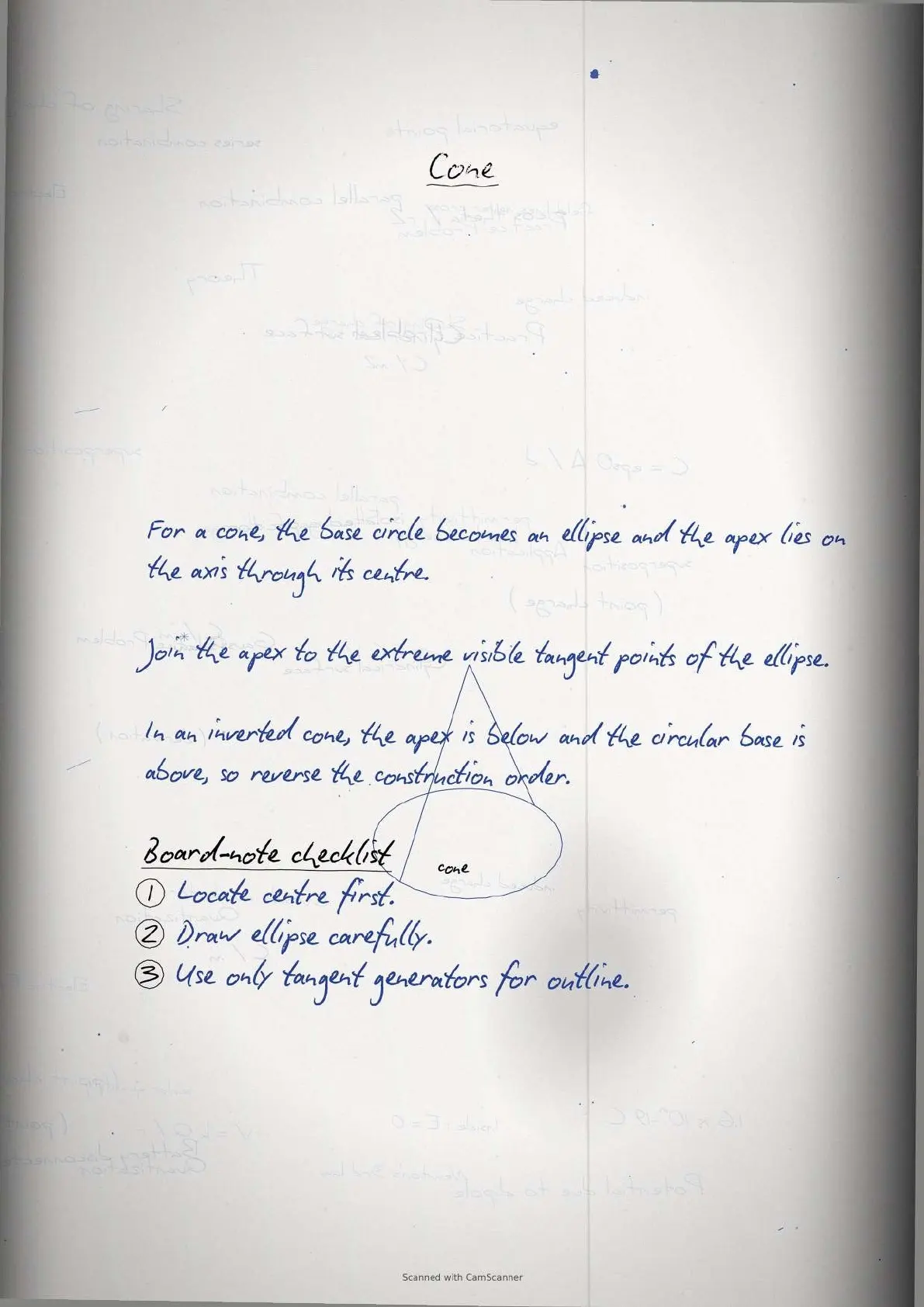
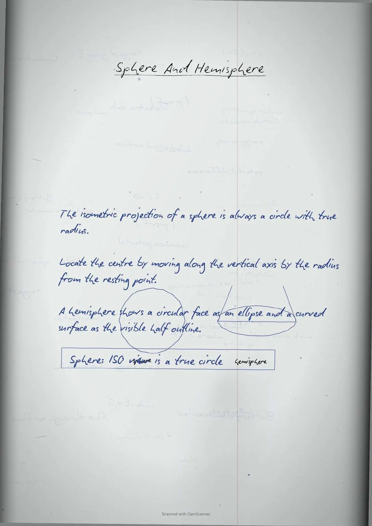
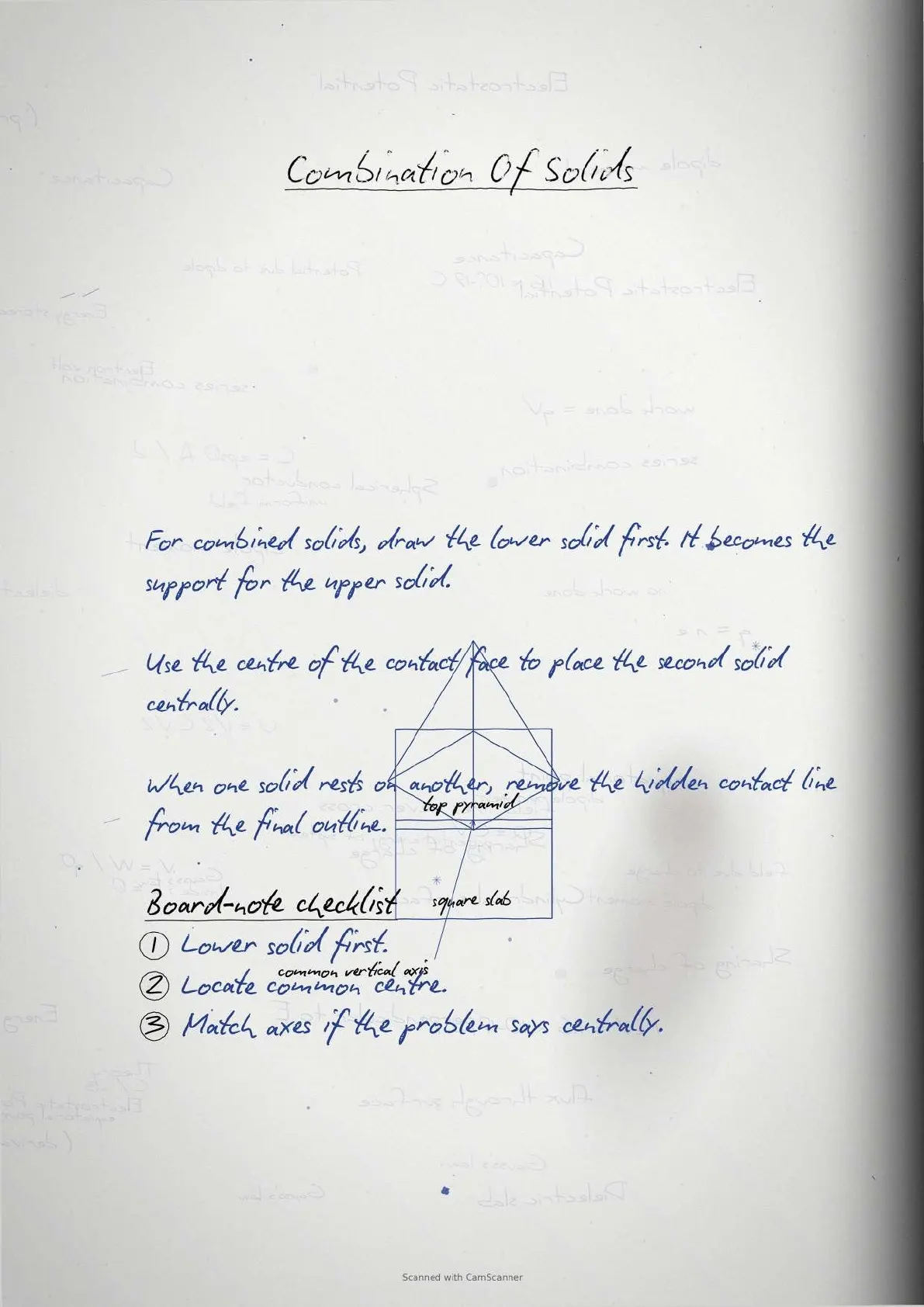
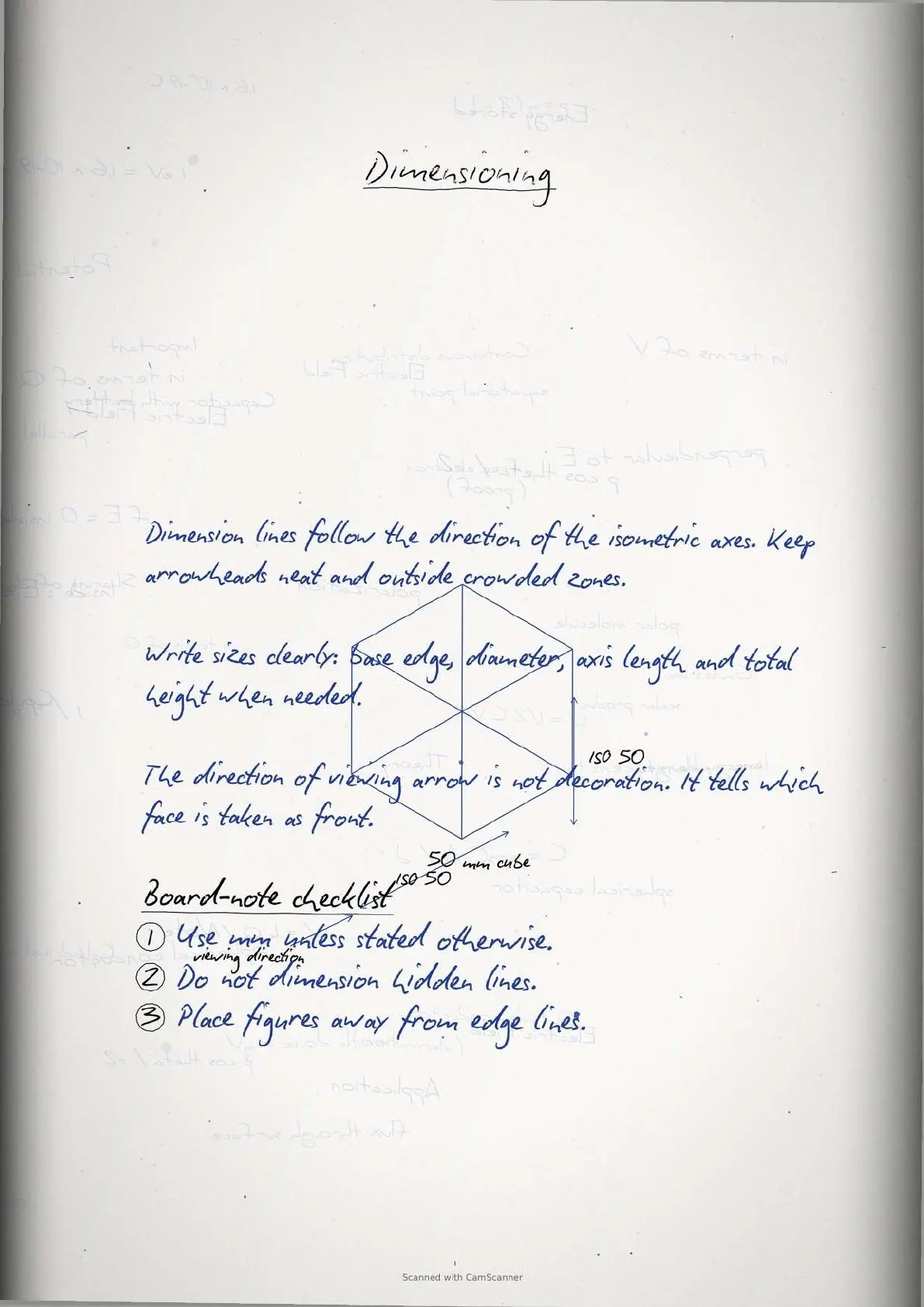
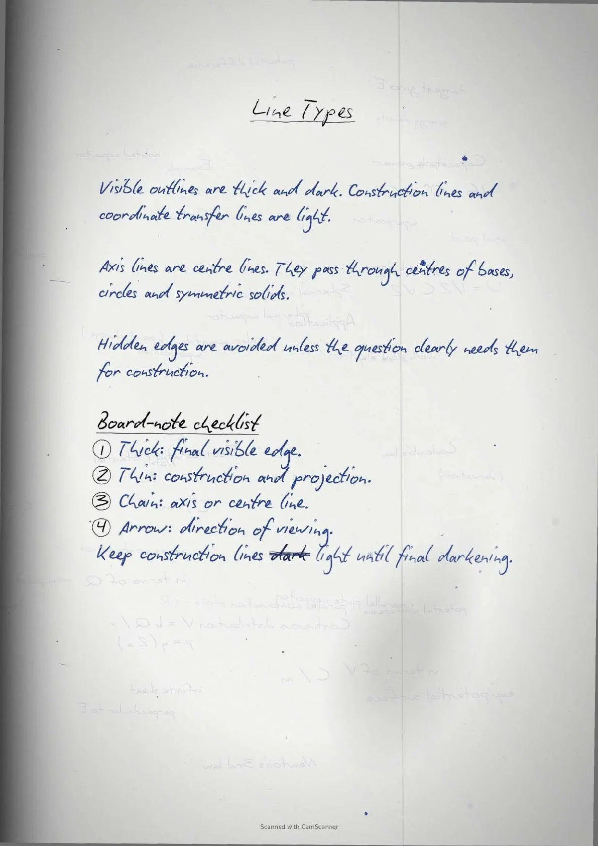
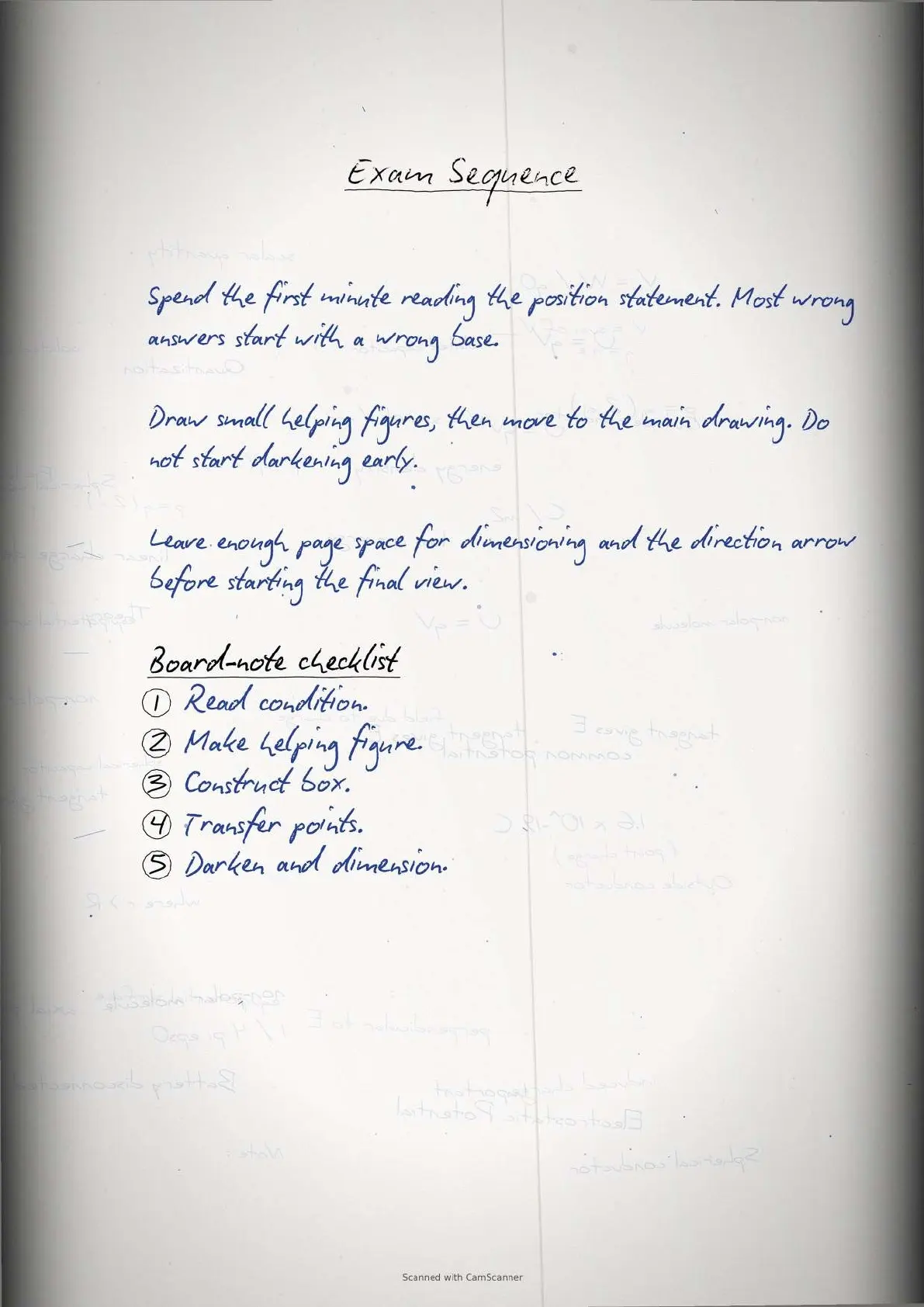
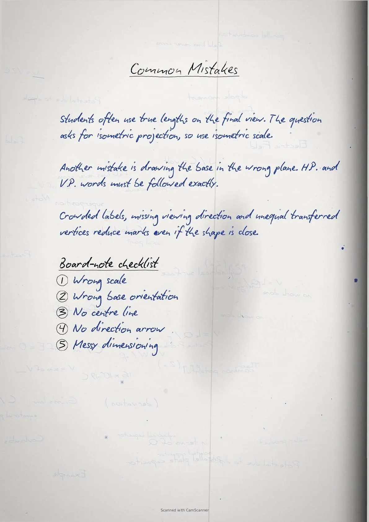
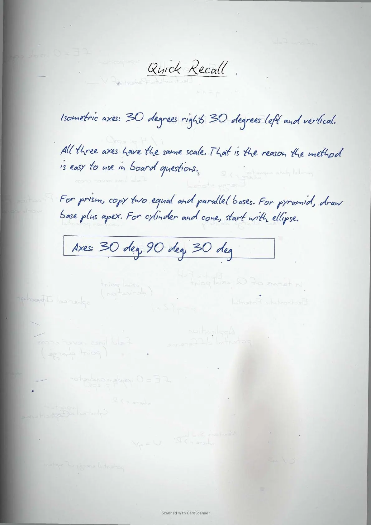
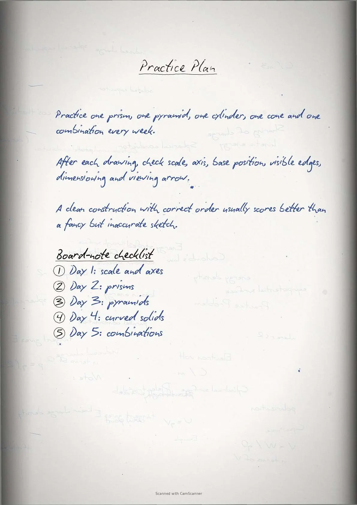
These Engineering Graphics handwritten notes are mapped to the 2026-27 CBSE syllabus and checked against the official Class XII Engineering Graphics book used for isometric projection practice.
Student Feedback
In a Collegedunia poll of 8,450 Class 12 skill-subject students, 71% said hand-drawn construction steps helped them revise Engineering Graphics faster than typed summaries. Most students finished one pass of this chapter in about 28 minutes.
Source: 2026-27 Collegedunia Class 12 Engineering Graphics revision poll.
Isometric Projection of Solids: What These Handwritten Notes Include
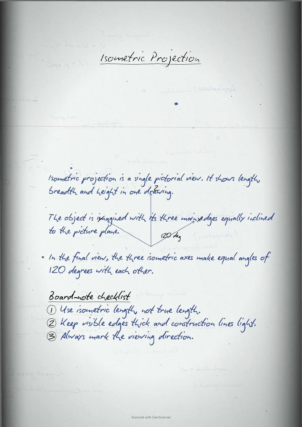
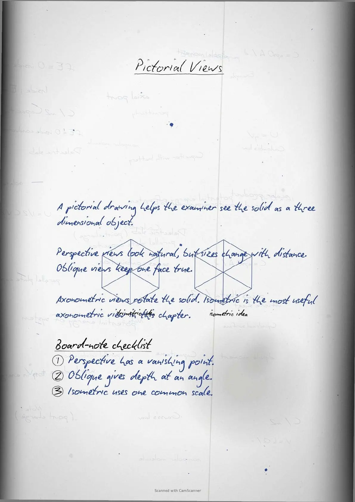
The handwritten notes start with the idea of a one-plane pictorial view. They explain why the three principal axes appear equally inclined and why the final drawing uses isometric length, not true length.
- Types of pictorial views: perspective, oblique and axonometric.
- Isometric axes at 120 degrees and the 30 degree drawing setup.
- Clear difference between helping figure and final isometric view.
- Practice-ready notes for cube, prism, pyramid, cylinder, cone and sphere.
Isometric Scale and Construction Method for Class 12 Boards
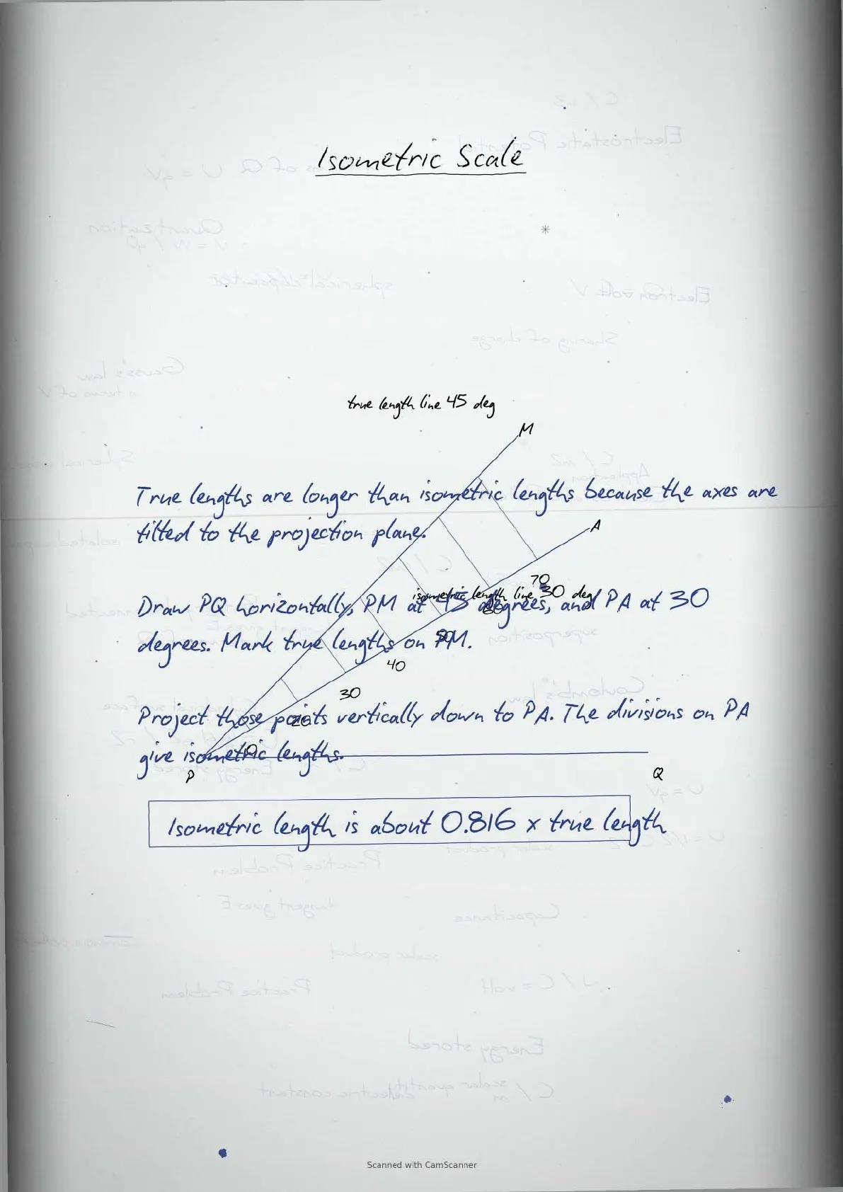
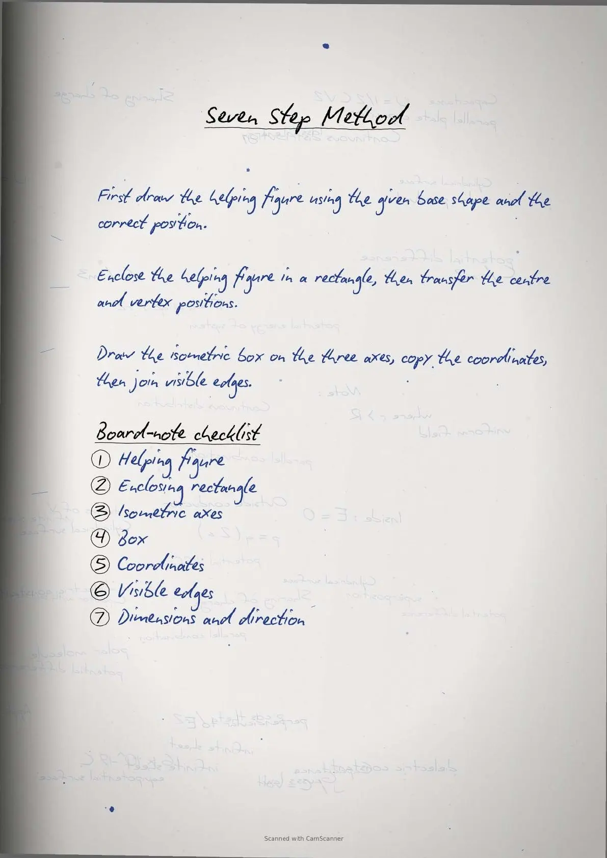
Isometric scale is the scoring base of this chapter. The notes show how to draw true lengths on the 45 degree line and transfer them to the 30 degree isometric line. This keeps every final measurement consistent.
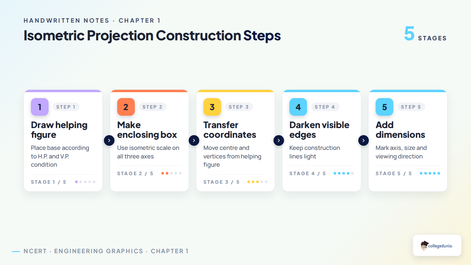
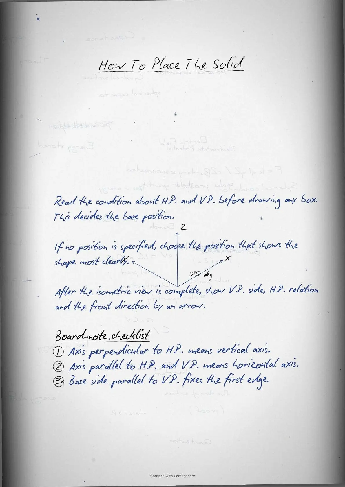
- Draw the base with the given H.P. and V.P. condition.
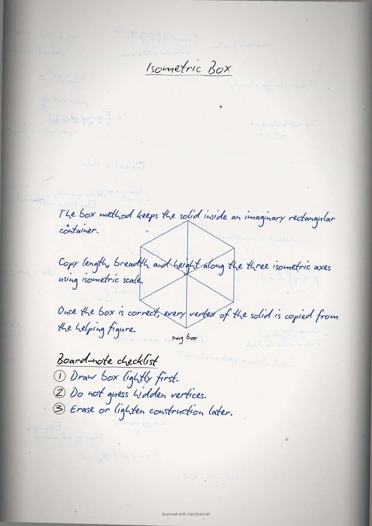
- Make an enclosing rectangle or box around the helping figure.
- Transfer centre points and vertices to the isometric box.
- Darken visible edges only after checking all coordinates.
Isometric Projection Versus True Shape Drawing
A common mistake is mixing the true-shape helping view with the final isometric view. The helping view gives accurate base geometry. The final view shows the solid in three dimensions using isometric scale.
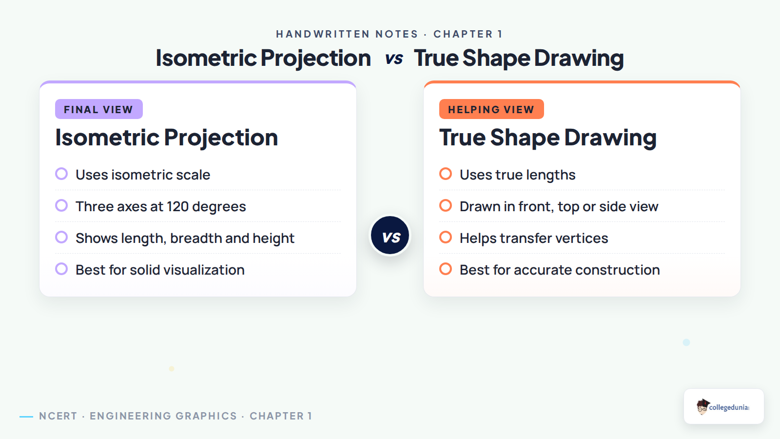
| Part | Used For | Length Used |
|---|---|---|
| Helping figure | Base shape and vertex transfer | True length |
| Isometric box | Final 3D construction | Isometric length |
| Final outline | Answer sheet presentation | Dark visible edges |
Isometric Projection Explained for Class 12 Engineering Graphics
Source: VISHWAKARMA ENGINEERING DRAWING CLASSES on YouTube
Solids Covered in the Isometric Projection Handwritten Notes
The PDF follows the board drawing order. Each solid is treated as a construction problem, not as a theory paragraph. This helps students practise the same sequence on the drawing sheet.
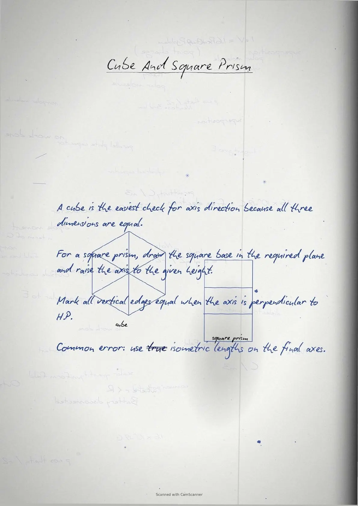
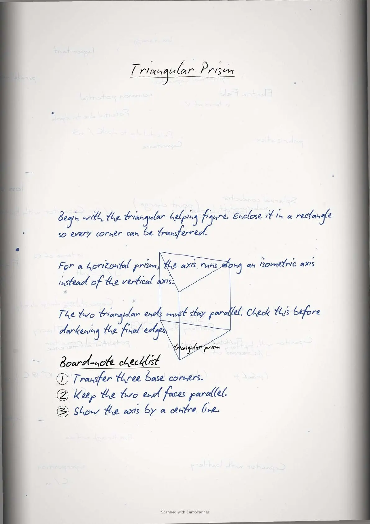
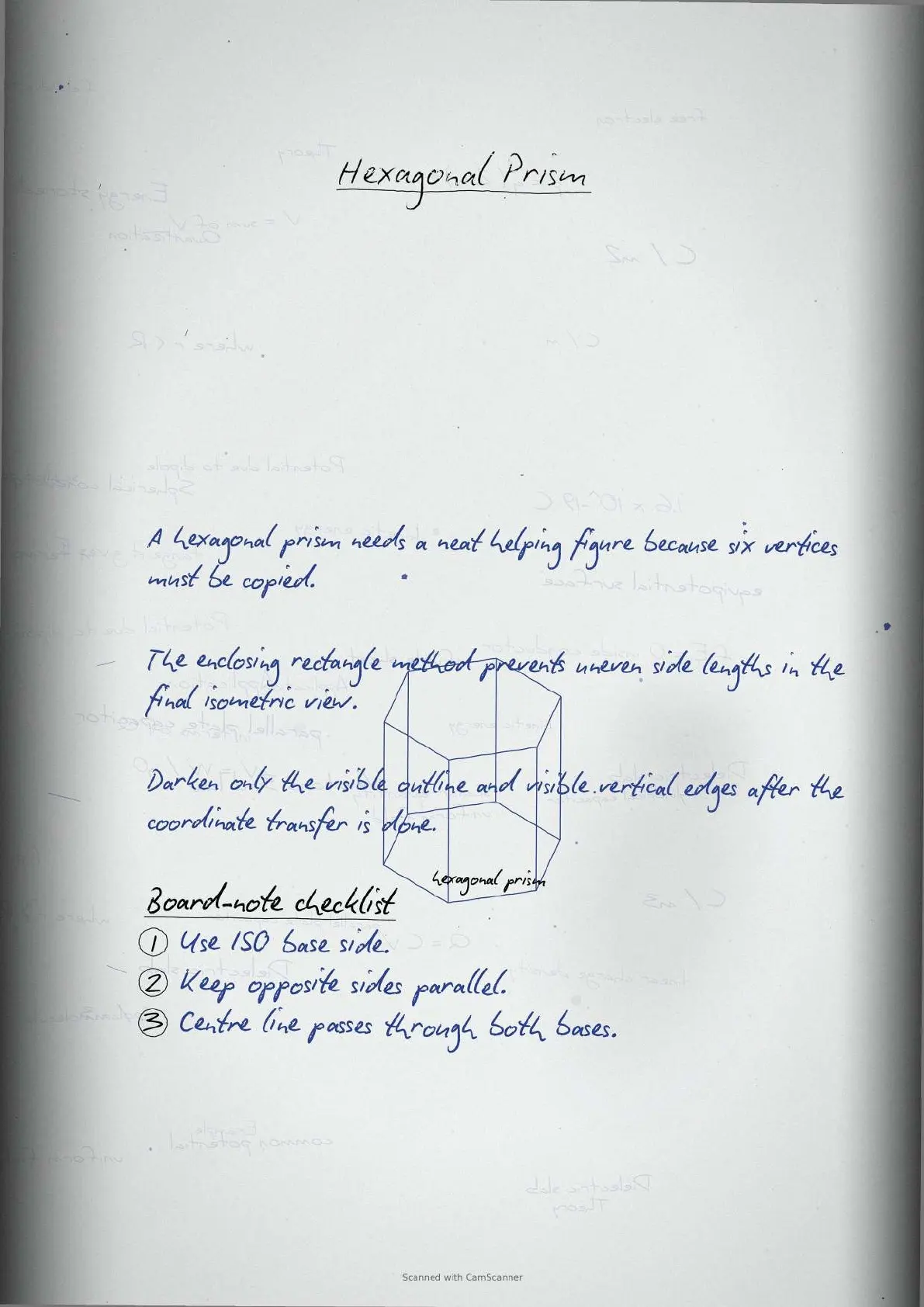
- Prisms: cube, square prism, triangular prism and hexagonal prism.
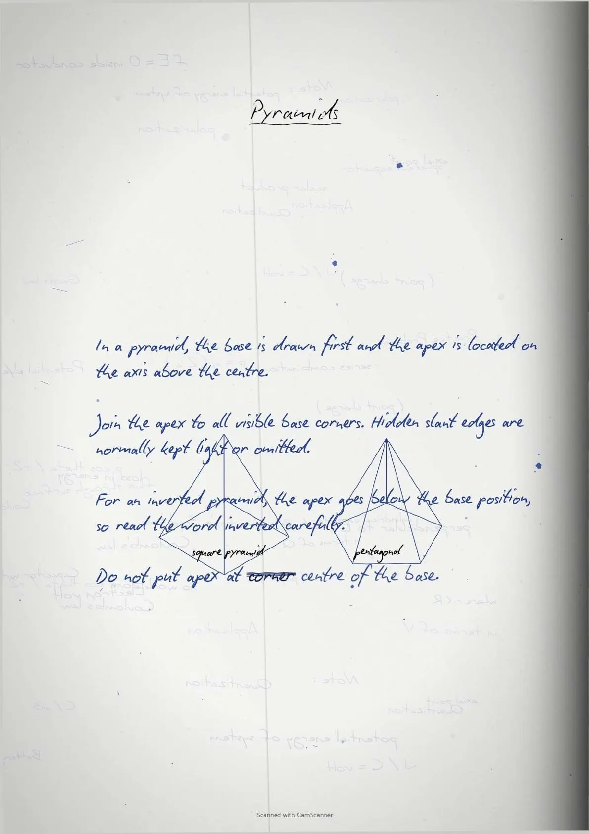
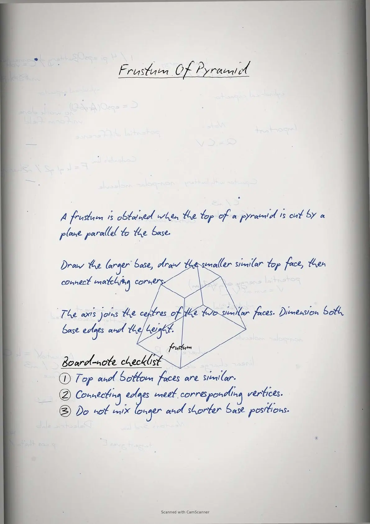
- Pyramids: square, pentagonal and inverted pyramid setups.
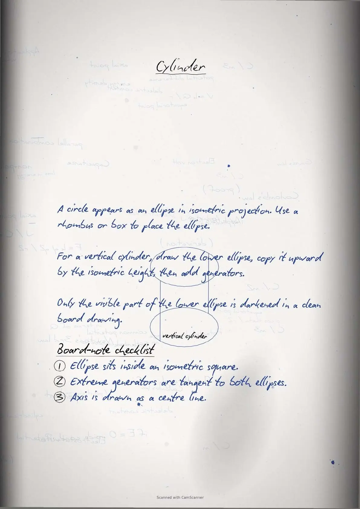
- Curved solids: cylinder, cone, sphere and hemisphere.
- Combinations: lower solid first, then upper solid on the common centre.
Common Mistakes in Isometric Projection of Solids
Engineering Graphics marks are lost through small construction errors. The notes flag these errors in the margin so students can avoid them while practising.
- Using true length on the final isometric axes.
- Drawing the base in the wrong plane after reading H.P. or V.P. carelessly.
- Forgetting the centre line for prisms, cylinders and cones.
- Leaving out the direction of viewing arrow and dimension labels.
Other Resources for Isometric Projection of Solids Class 12
| Resource | Use it for |
|---|---|
| Class 12 Notes Reference | See how structured revision notes are arranged. |
| Class 12 Handwritten Notes Reference | Compare handwritten revision layout and flow. |
| Computer Networks Handwritten Notes | Use another diagram-heavy handwritten PDF for revision style. |
All Chapters Handwritten Notes for Class 12 Revision
| Chapter | Handwritten Notes |
|---|---|
| Engineering Graphics Chapter 1 | Isometric Projection of Solids Handwritten Notes |
| Maths Chapter 1 | Relations and Functions Handwritten Notes |
| Maths Chapter 10 | Vector Algebra Handwritten Notes |
| Computer Science Chapter 11 | Data Communication Handwritten Notes |
Isometric Projection of Solids Class 12 Handwritten Notes FAQs
Ques. What is included in the Isometric Projection of Solids handwritten notes?
Ans. The PDF includes isometric scale, axes, helping figures, construction steps, prisms, pyramids, cylinders, cones, spheres and combination of solids.
Ques. Are these handwritten notes useful for CBSE Class 12 Engineering Graphics?
Ans. Yes. The notes follow the Class XII Engineering Graphics isometric projection unit and match the 2026-27 CBSE drawing practice pattern.
Ques. Why is isometric scale important in this chapter?
Ans. Isometric scale gives the foreshortened length used in the final projection. Using true length in the final view is a common drawing error.
Ques. How should students revise this PDF before the board exam?
Ans. First revise the scale and seven-step construction method, then practise one prism, one pyramid, one curved solid and one combination drawing.



Comments