



The Machine Drawing Rod Joints Class 12 handwritten notes have been prepared for quick Engineering Graphics revision according to the 2026-27 CBSE syllabus. The PDF covers cotter basics, sleeve and cotter joint, gib and cotter joint, sectioning rules, assembly views and disassembly views.
- Best for: last-minute drawing-sheet revision before boards.
- PDF includes: 24 handwritten pages with colour-coded rod joint diagrams.
- Focus area: sleeve and cotter, gib and cotter, sectioning and projection.
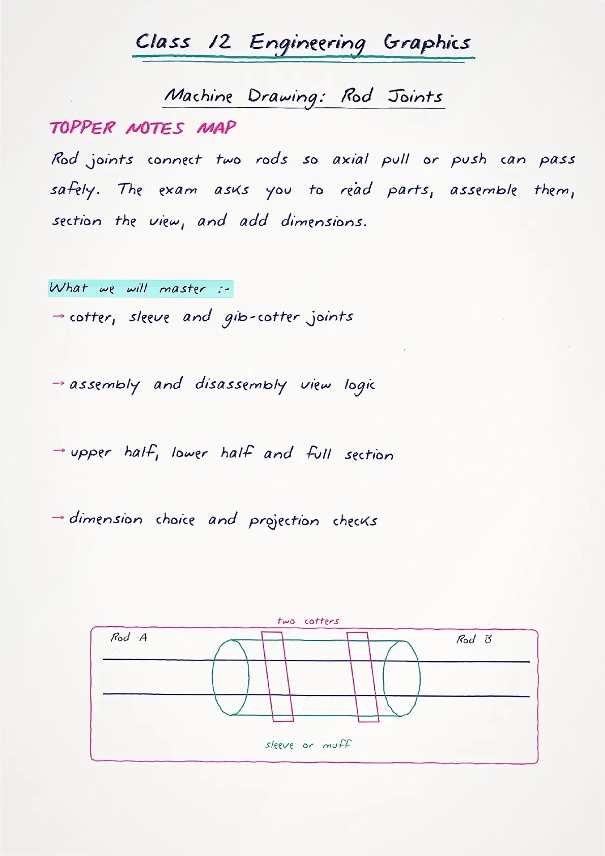
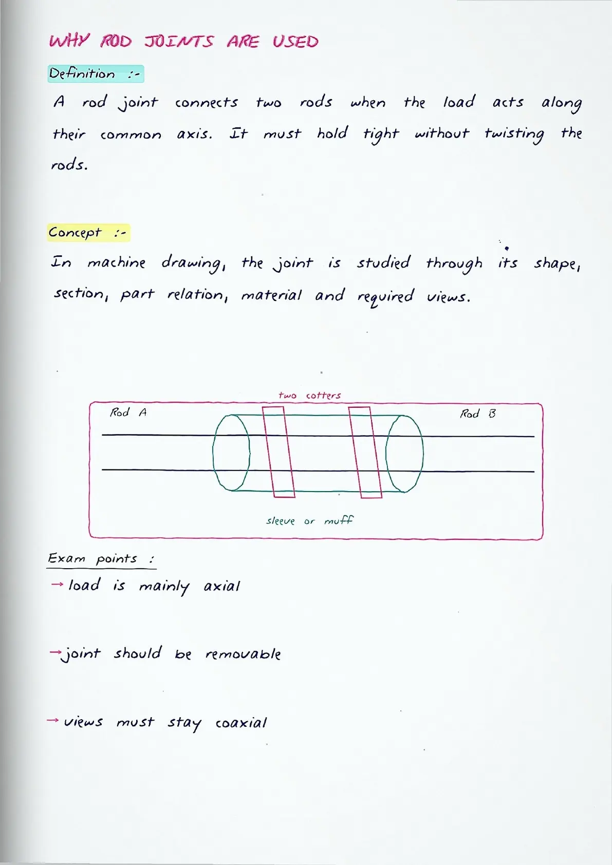
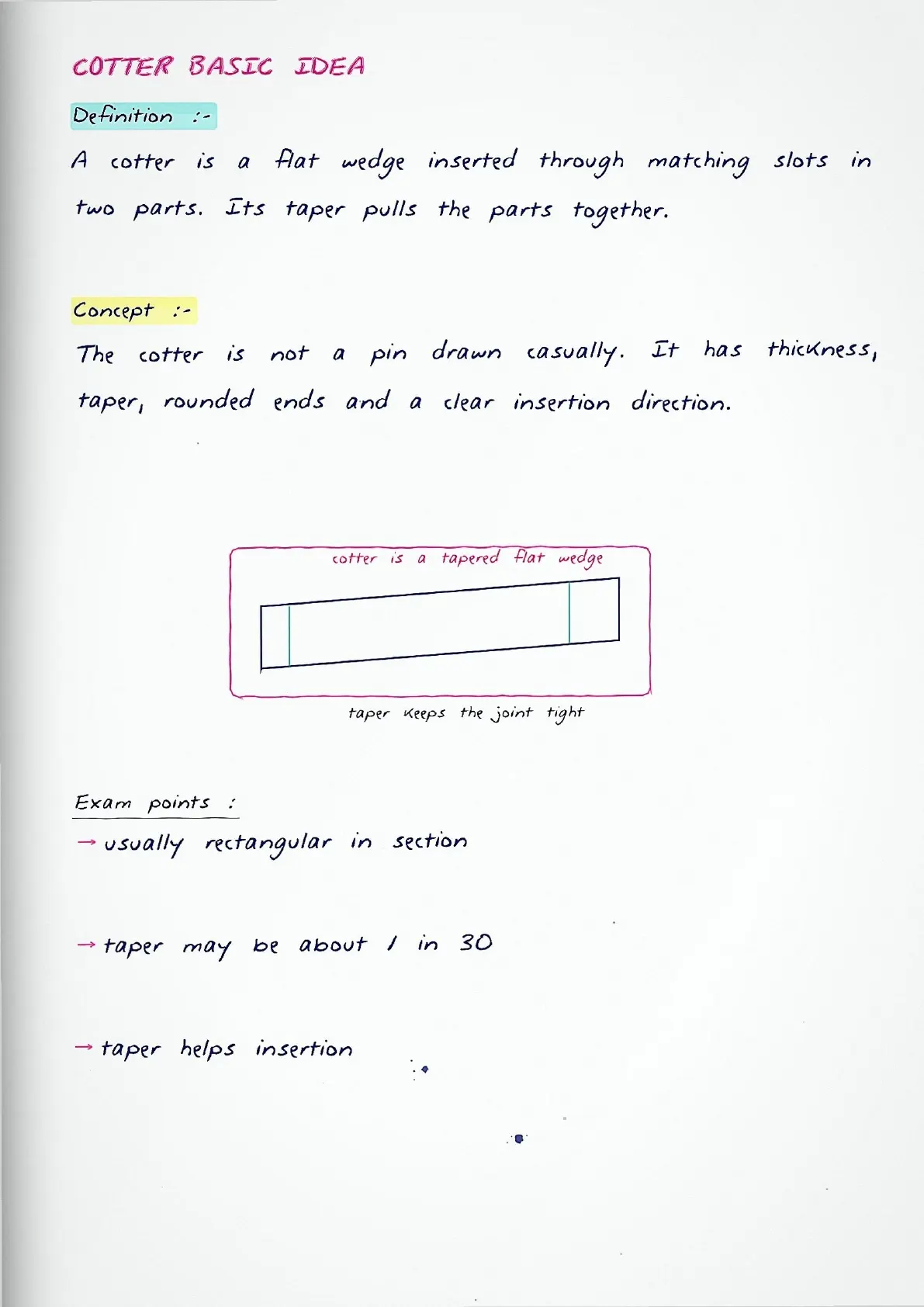
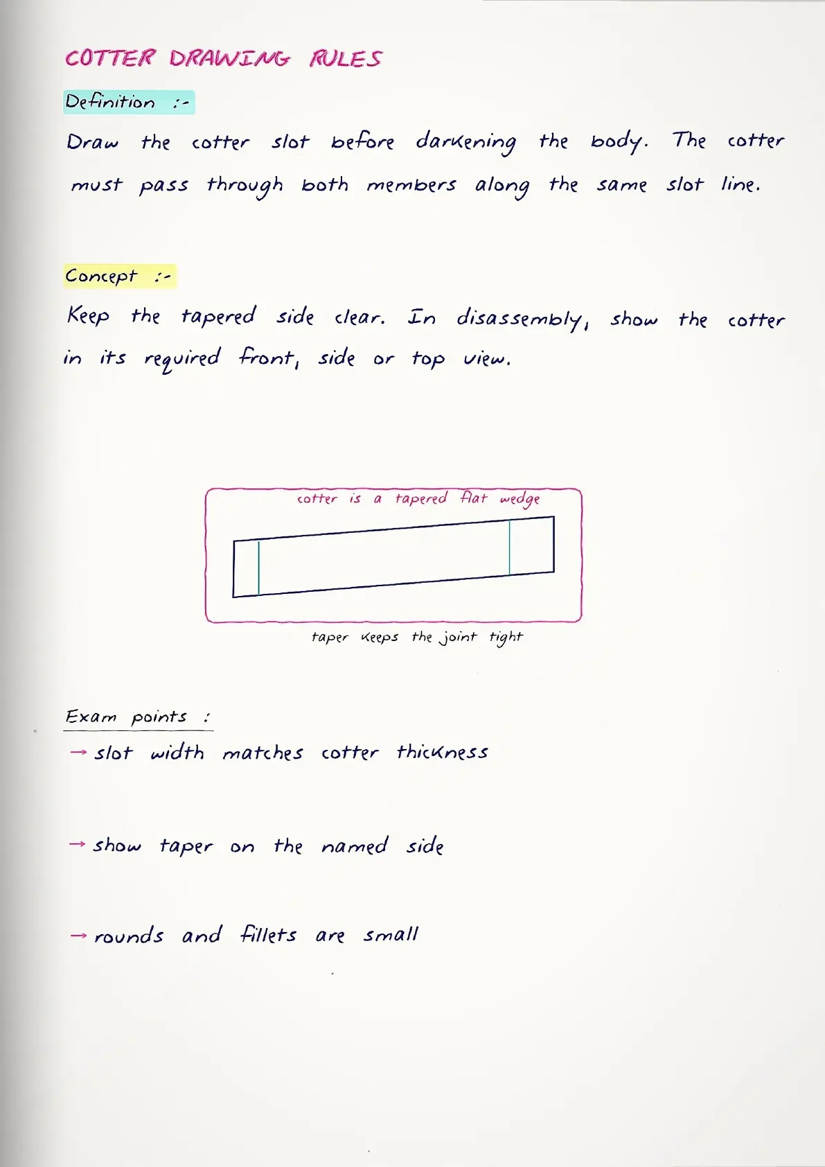
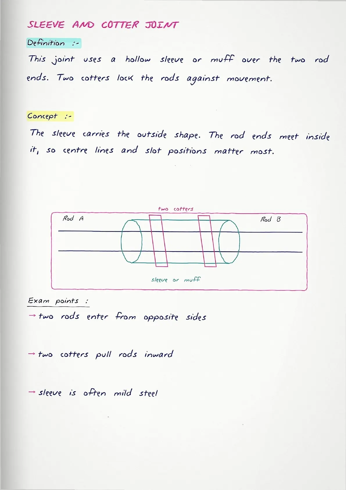
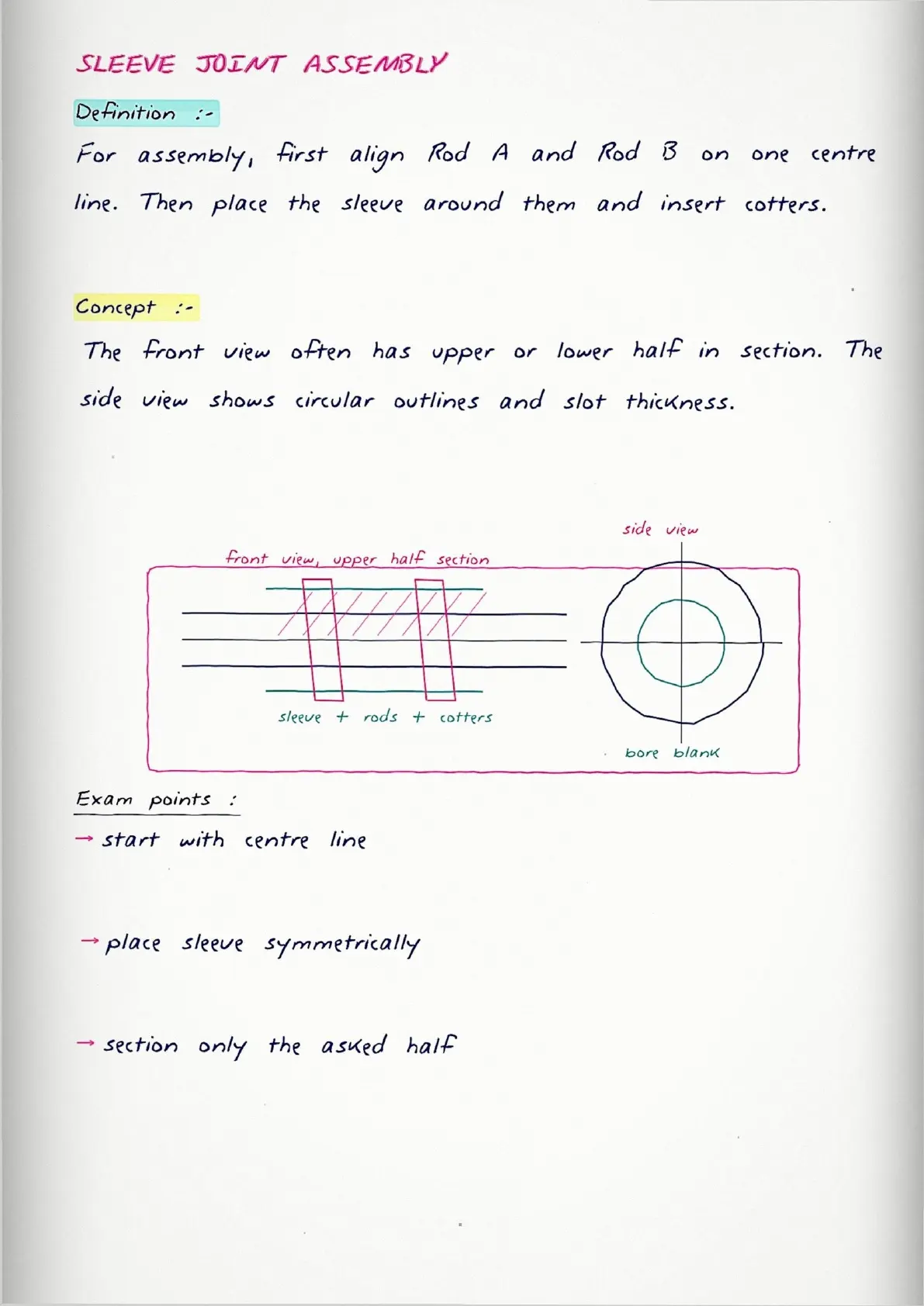
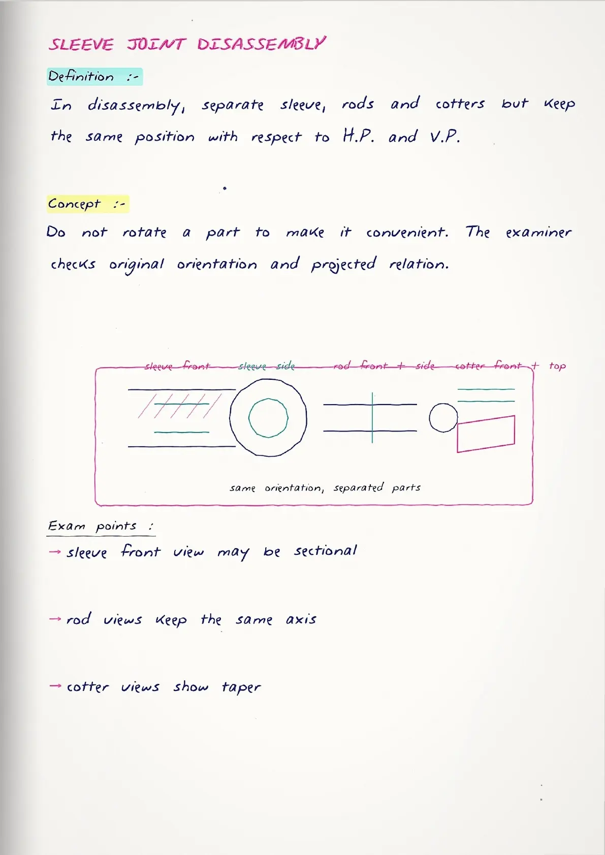
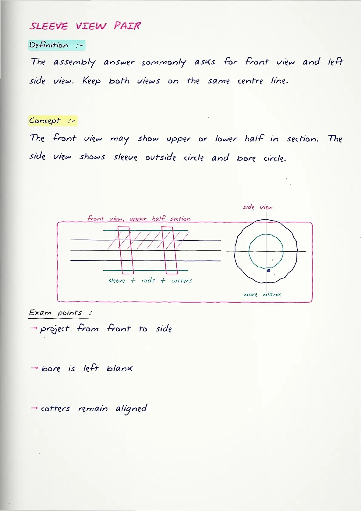
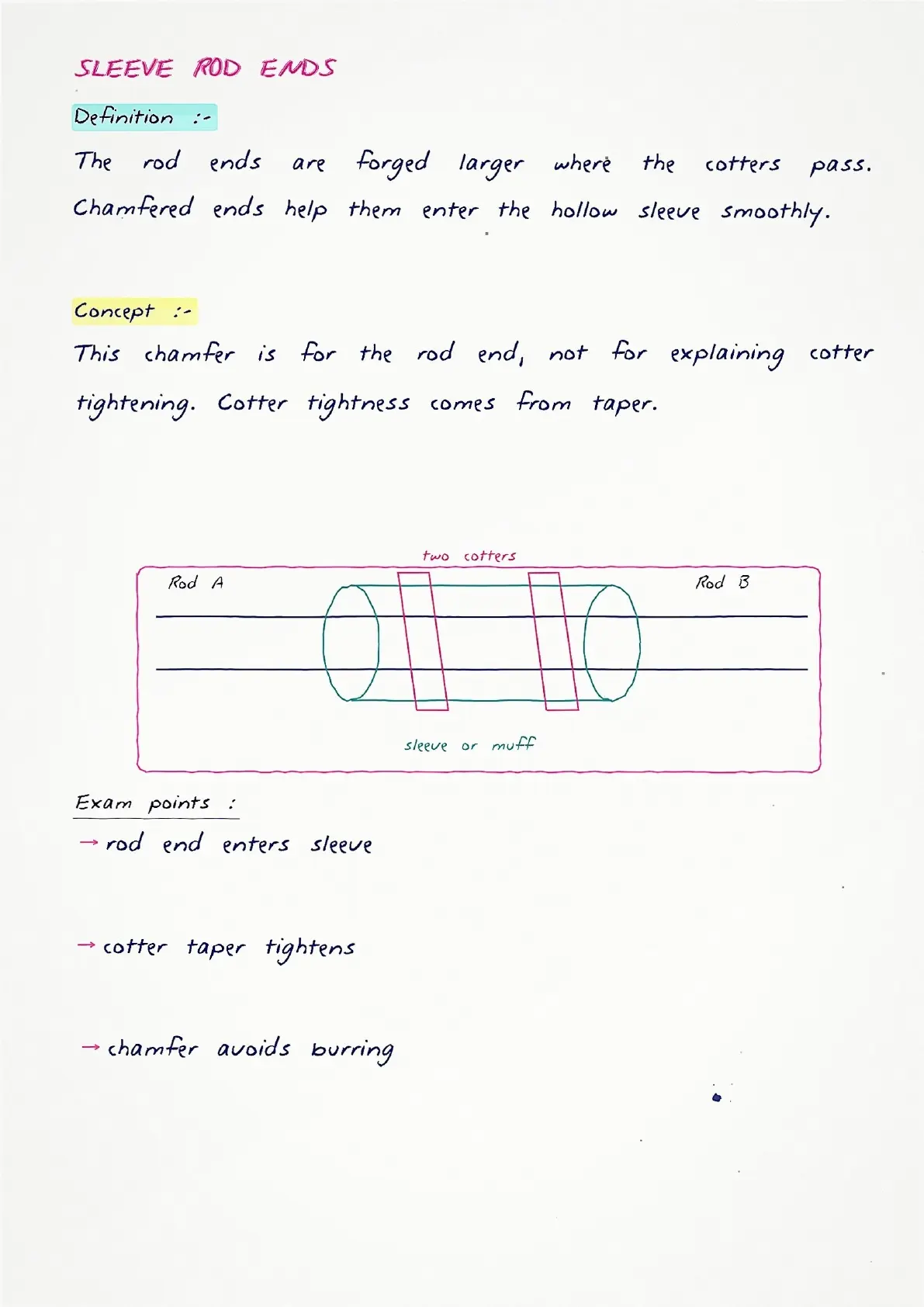
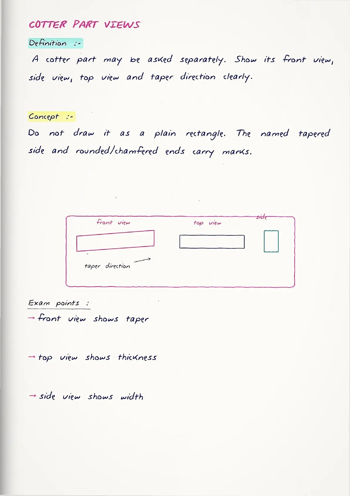
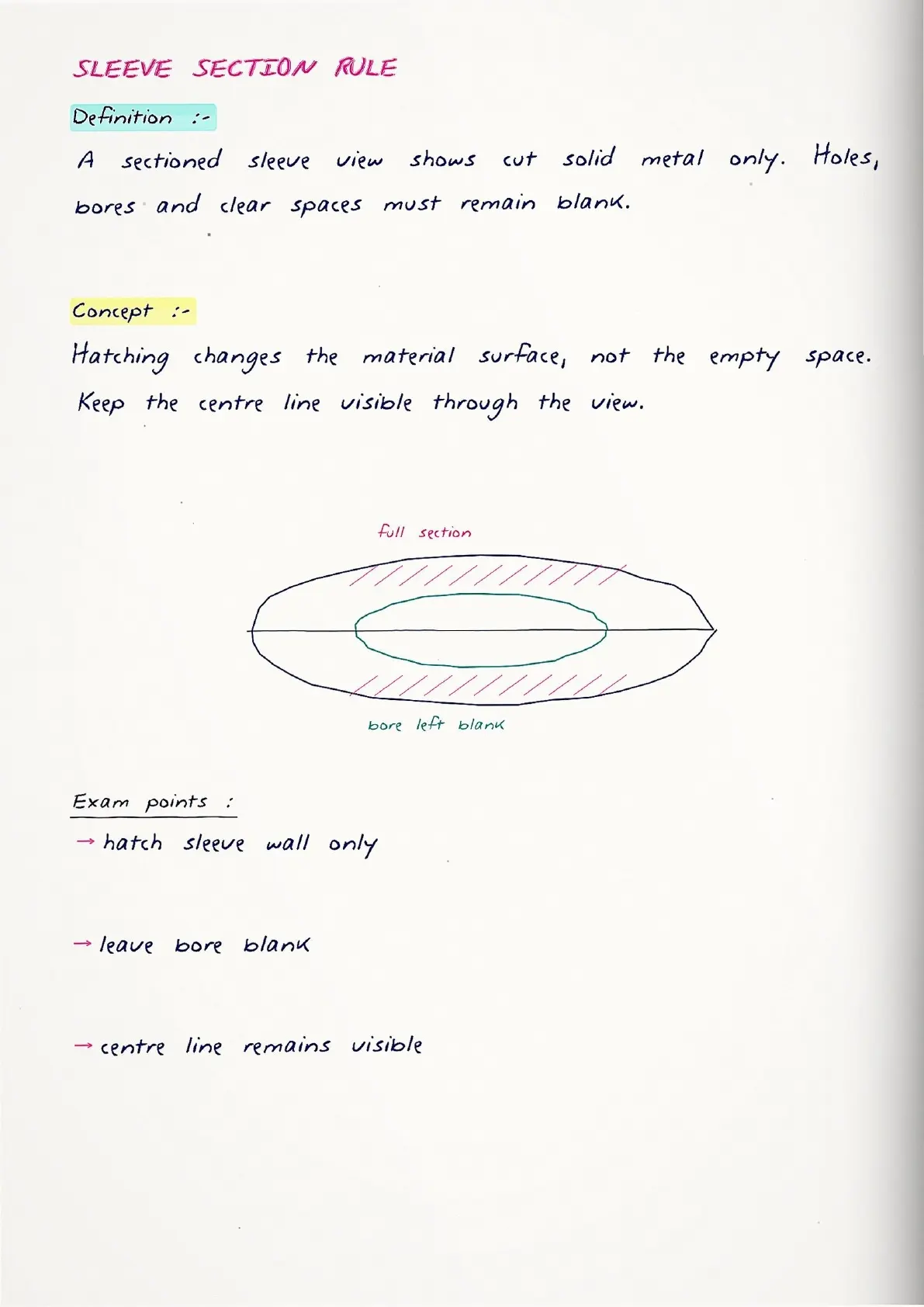
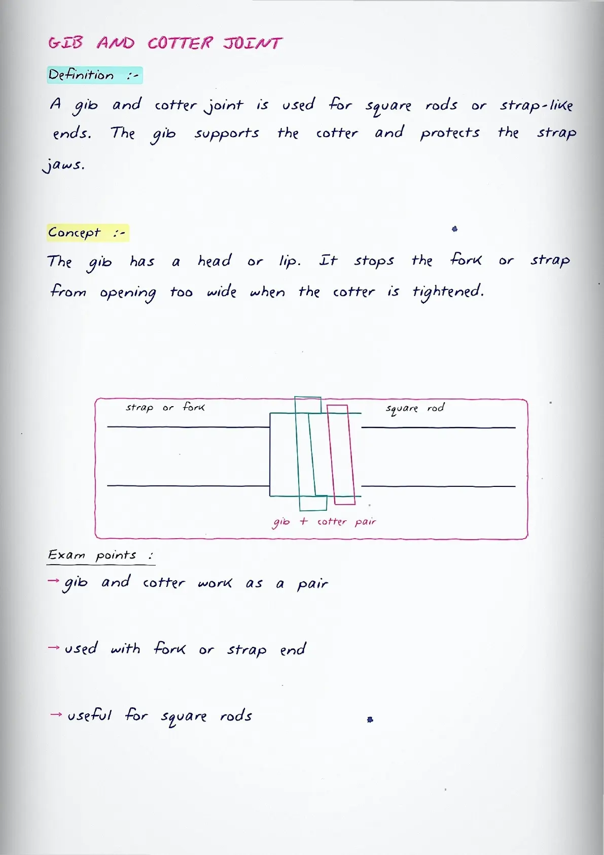
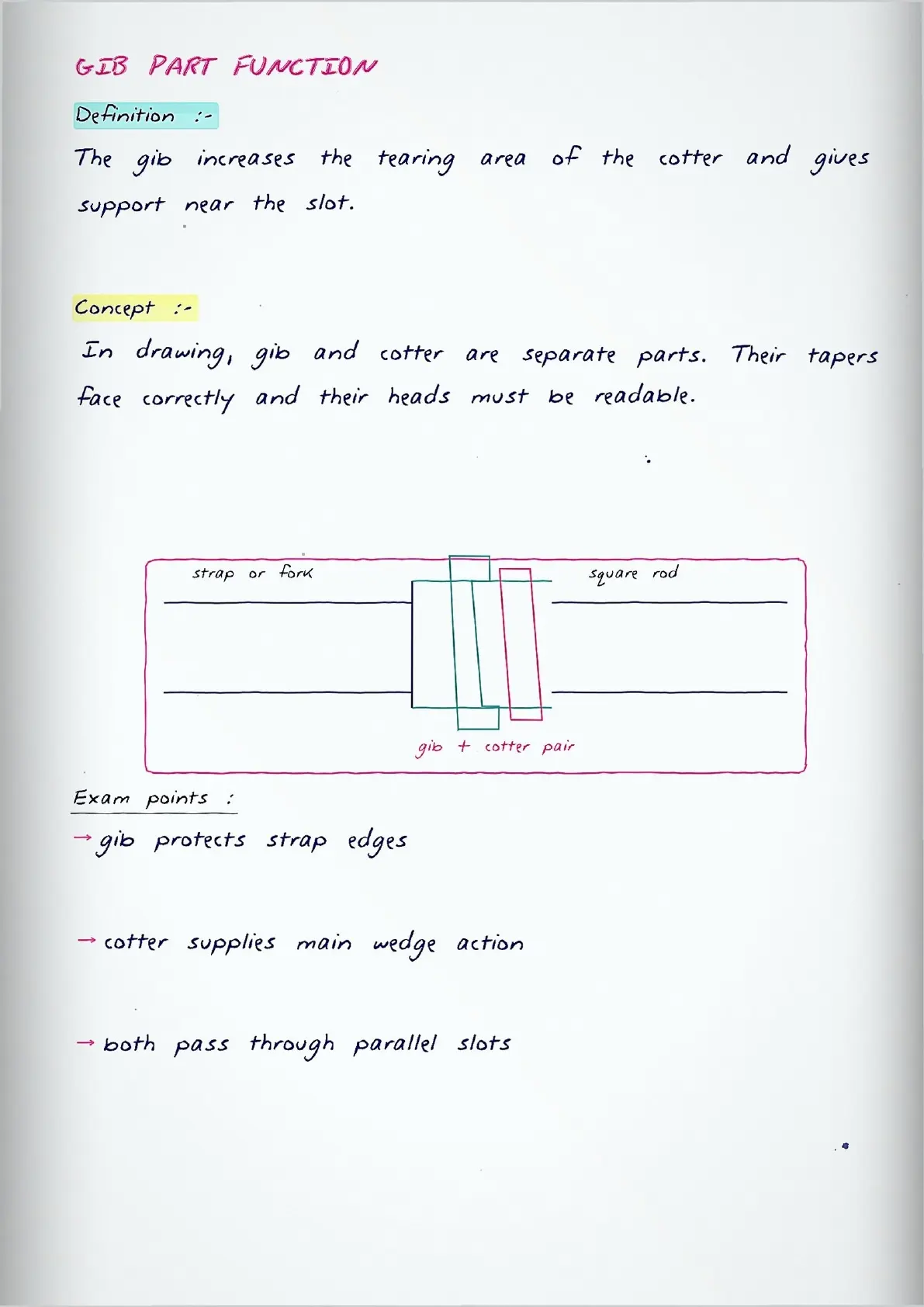
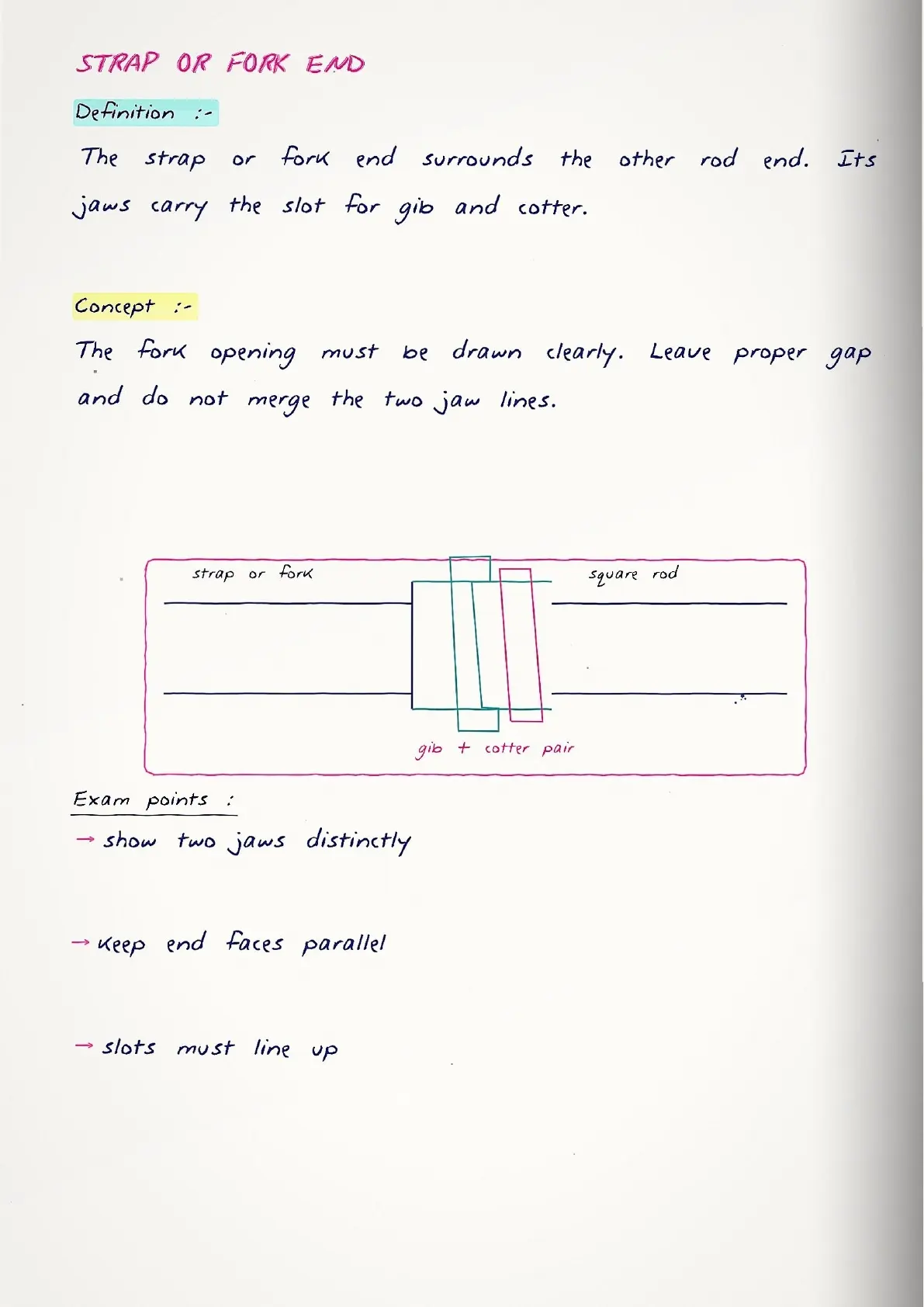
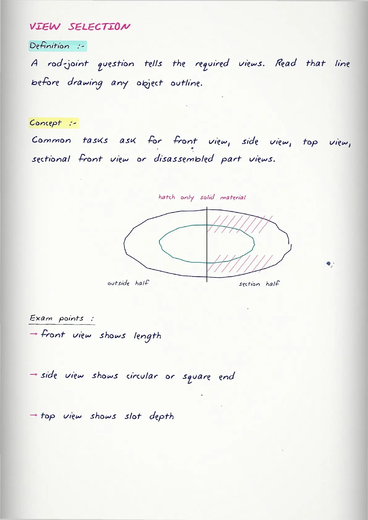
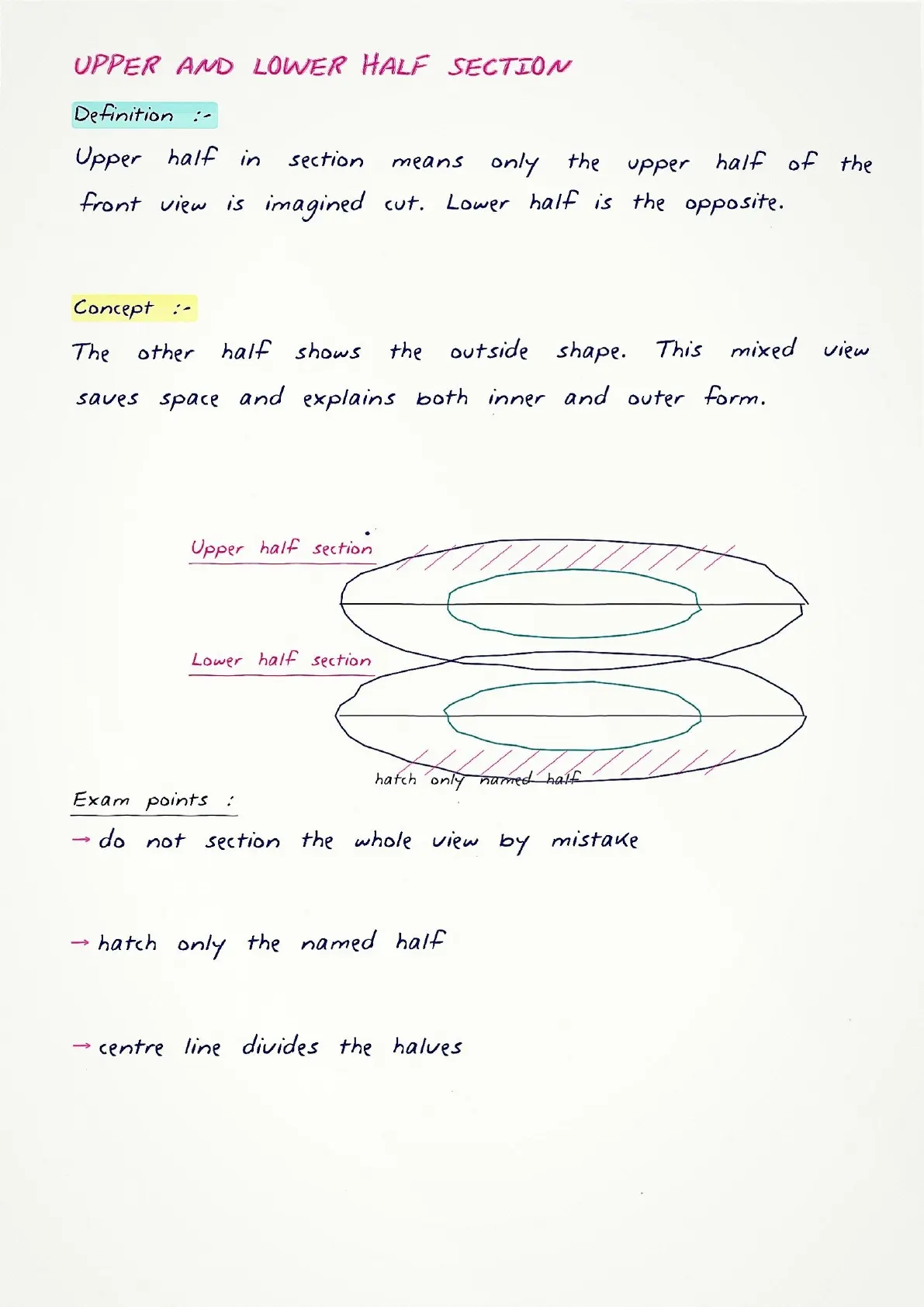
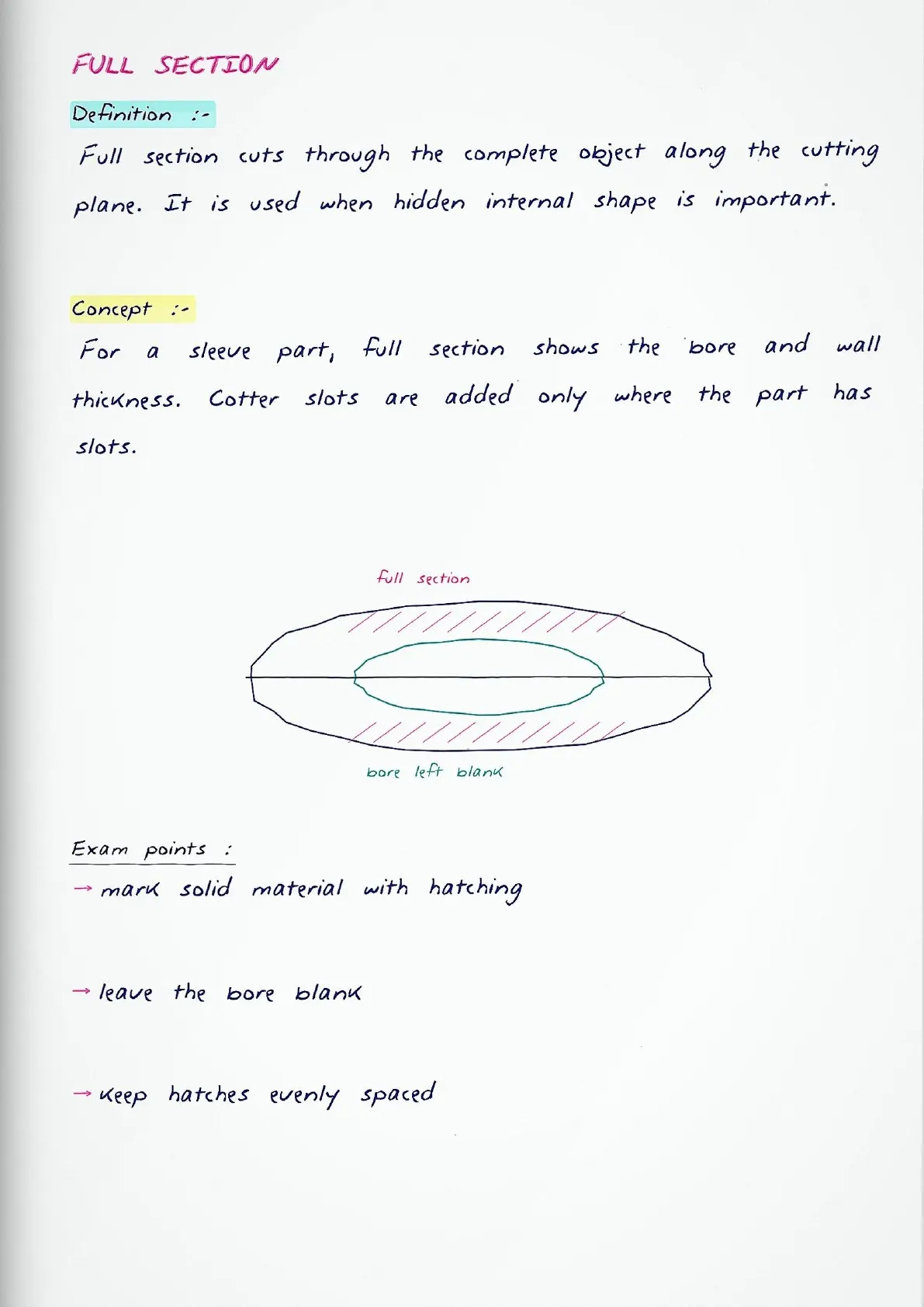

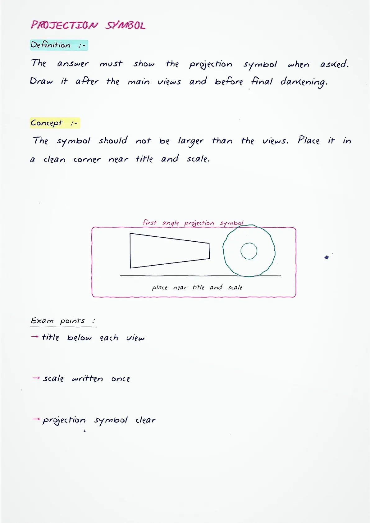
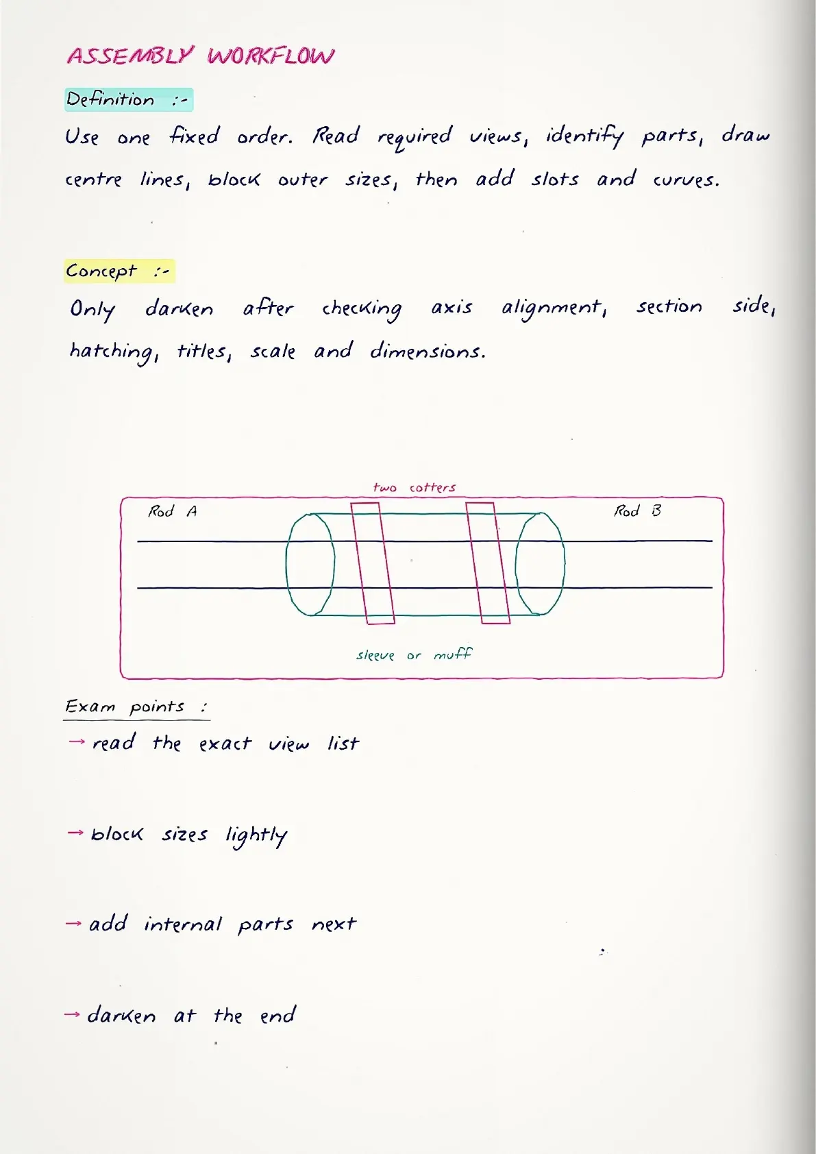
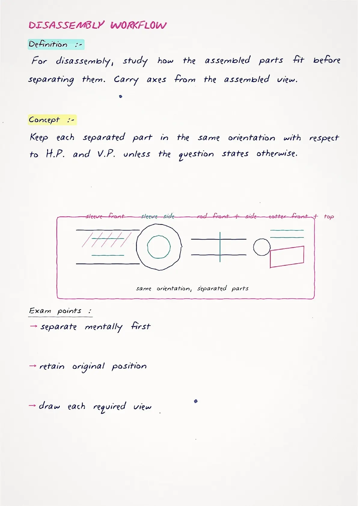
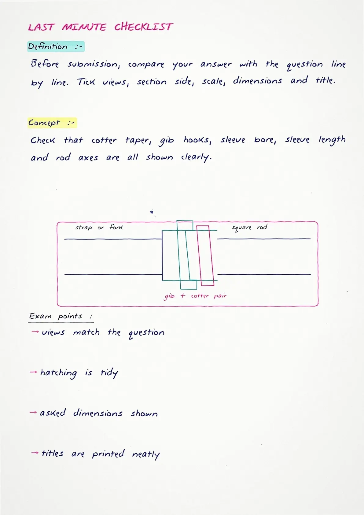
These handwritten notes follow the official Class XII Engineering Graphics Rod Joints chapter and focus on the view logic students need while drawing sleeve, cotter and gib-cotter questions.
Student Feedback
In a Collegedunia poll of 11,260 Class 12 Engineering Graphics students, 76% of students said rod-joint part-view practice helped them avoid sectioning mistakes before the 2026 boards.
Source: 2026-27 Collegedunia Class 12 Engineering Graphics revision poll.
What Machine Drawing Rod Joints Class 12 Handwritten Notes Include
The notes begin with the purpose of rod joints and the role of a cotter as a flat tapered wedge. They then move into sleeve and cotter joint, gib and cotter joint, upper half section, lower half section and full section.
- Cotter taper, slot alignment and insertion direction.
- Sleeve front view, side view and disassembly relation.
- Gib hooks, cotter support and square rod connection.
- Projection symbol, title, scale and asked dimensions.
Sleeve and Cotter vs Gib and Cotter Joint for Class 12 Boards
Sleeve and cotter joint is used for two round rods that meet inside a hollow sleeve. Gib and cotter joint is used where a fork or strap end holds a square rod. The biggest exam difference is the part relation, not the neatness of the outline.
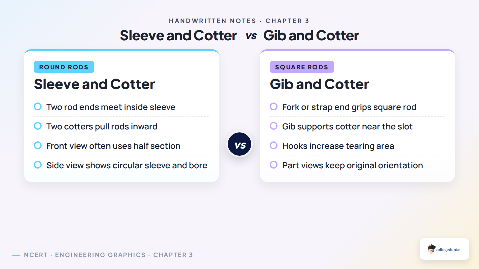
| Point | Sleeve and Cotter Joint | Gib and Cotter Joint |
|---|---|---|
| Rod type | Round rods | Square or rectangular rods |
| Main parts | Sleeve, two rods and two cotters | Fork or strap, square rod, gib and cotter |
| View focus | Sectioned sleeve and circular side view | Fork opening, gib hooks and aligned slot |
Rod Joint Drawing Workflow for Class 12 Engineering Graphics
A rod-joint answer should be drawn in a fixed order. Read the required views first, set the centre lines, block the main parts, then add slots, hatching, dimensions and projection symbol. Do not rotate parts during disassembly unless the question clearly asks for a new position.
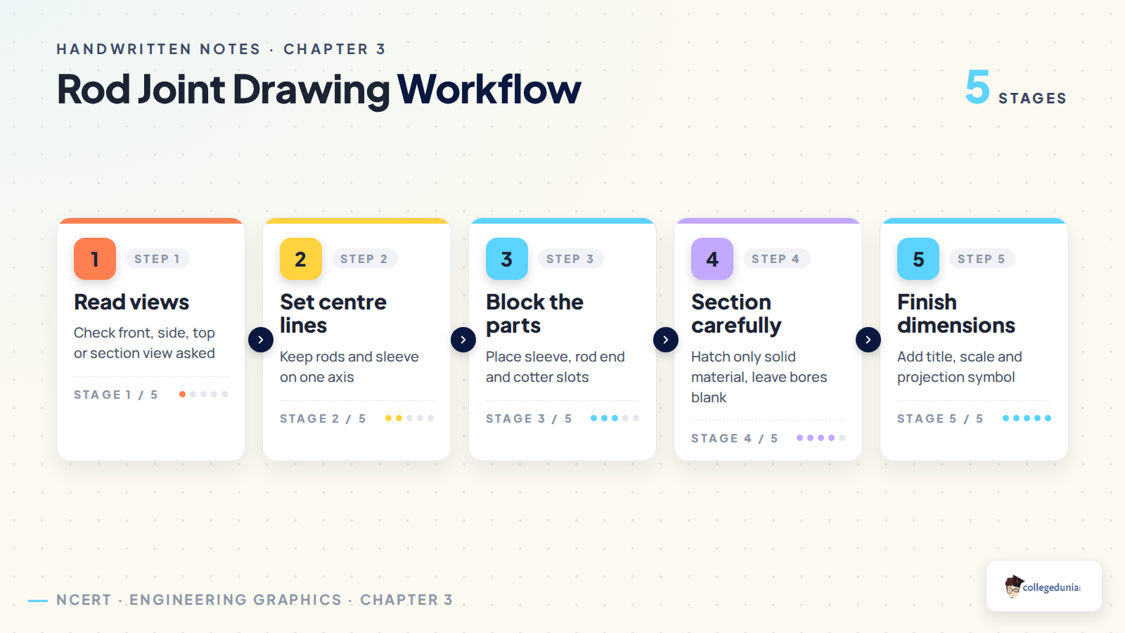
- Keep Rod A and Rod B on one centre line.
- Hatch only the solid cut material in section views.
- Leave the bore and empty slot space blank.
- Print every title clearly below the view.
Sleeve and Cotter Joint Assembly Video for Class 12
Source: YouTube Engineering Graphics lesson on sleeve and cotter joint assembly
Common Rod Joint Drawing Mistakes in Machine Drawing
Most rod-joint mistakes happen after the main shape is correct. Students lose marks when the section side, cotter taper or part orientation is wrong.
- Drawing the cotter like a straight pin with no taper.
- Hatching the bore or other empty space.
- Mixing sleeve side view with front section.
- Forgetting first-angle projection symbol, scale or asked dimensions.
Other Resources for Machine Drawing Rod Joints Class 12
| Resource | Use it for |
|---|---|
| Machine Drawing Bearings Handwritten Notes | Revise the previous machine drawing unit. |
| Isometric Projection Handwritten Notes | Practise earlier Engineering Graphics view logic. |
| Computer Networks Handwritten Notes | Use another diagram-heavy handwritten revision PDF. |
All Chapters Handwritten Notes for Class 12 Revision
| Chapter | Handwritten Notes |
|---|---|
| Engineering Graphics Chapter 1 | Isometric Projection of Solids Handwritten Notes |
| Engineering Graphics Chapter 2 | Machine Drawing Bearings Handwritten Notes |
| Engineering Graphics Chapter 3 | Machine Drawing Rod Joints Handwritten Notes |
| Maths Chapter 10 | Vector Algebra Handwritten Notes |
Machine Drawing Rod Joints Class 12 Handwritten Notes FAQs
Ques. What is included in the Machine Drawing Rod Joints Class 12 handwritten notes?
Ans. The PDF includes cotter basics, sleeve and cotter joint, gib and cotter joint, section views, assembly workflow and disassembly workflow.
Ques. Are sleeve and cotter joint views covered in the PDF?
Ans. Yes. The notes cover sleeve front view, side view, sectioning, rod alignment, cotter placement and disassembly relation.
Ques. Why is gib and cotter joint important for Class 12 Engineering Graphics?
Ans. Gib and cotter joint teaches students how a fork or strap end grips a square rod, and how gib hooks support the cotter near the slot.
Ques. How should students revise rod joints before the board exam?
Ans. Revise part names first, then practise one sleeve assembly view, one disassembly view, one gib-cotter sketch and one projection symbol.



Comments