



Content Curator
Buzzer is an electrical device that is used to get a buzzing or beeping sound when a potential difference is created or voltage is applied. It has different applications in offices, schools, quiz competitions, sports, and games. By building a circuit and making a buzzer, we will get an idea of how the circuit and potential difference in it will result in the functioning of the buzzer device.
Key Takeaways: Buzzer, buzzer circuit, flipper, buzzer test
How to make a Buzzer?
[Click Here for Sample Questions]
Make a buzzer at home to understand the working of an electrical circuit. As mentioned earlier, the buzzer is an electrical device that generates audible sound due to potential differences between source and sinks in the circuit. The buzzing or beeping sound is created by vibrations developed in the diaphragm of the device when the circuit is complete. When there is a break in the circuit, then the buzzing sound stops.
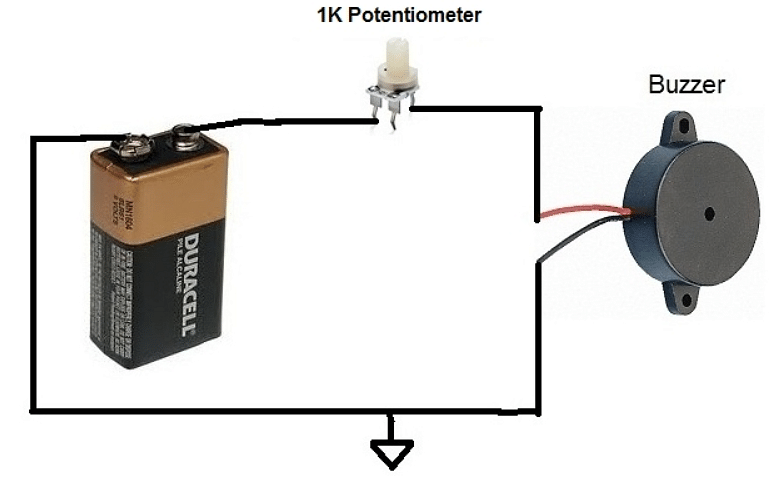
Buzzer Connection
Read More:
Buzzer Circuit
[Click Here for Sample Questions]
An electric circuit with a buzzer is called a buzzer circuit. It consists of a copper wire, nails, battery, an armature, and an electric buzzer. The armature is a revolving structure with an electric motor and the electric wire coils wound. It is used to generate potential difference or EMF (ElectroMotive Force). The armature is used as a key to connect or disconnect the circuit. It magnetized and demagnetised nails to act as a switch.
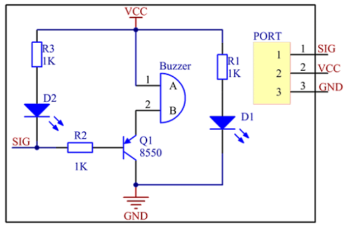
Buzzer Circuit
Read More: Difference between Fuse and Circuit breaker
Flipper
[Click Here for Sample Questions]
A bent copper wire is used as a flipper. It is so-called because it flips on/off the electrical circuit. A screw is used to secure the copper wire on a wooden board so that the copper wire of two ends would touch the armature. The red wire is connected to the battery holder to the flipper screw and the other wire from the armature screw to the key. In this set up it is possible for electricity to pass through the armature and enter the switch/key.

Buzzer set up
Read More:
Buzzer Test
[Click Here for Sample Questions]
If the key is pushed then a buzzing sound can be heard from the buzzer. If the sound is not heard, troubleshooting is to be done in the following ways.
- The wire of the flipper should touch the armature when it is in the upward position, and not touch in the downwards position.
- There should not be any loose connection in the circuit.

Troubleshooting the Buzzer Circuit
Read More:
Uses of Buzzers
[Click Here for Sample Questions]
- It is widely used in fire alarms in residential, institutional, commercial and industrial places.

Fire alarm Buzzer
- It is used in schools to ring bells.
- It is also used in quiz competitions.
- It is integrated with many electrical and electronic appliances such as printers, inverters, gaming devices, etc.
Things to Remember
- The buzzer is an electrical device that is used to get a buzzing or beeping sound.
- The buzzing or beeping sound is created by vibrations developed in the diaphragm of the device.
- The buzzer circuit consists of a copper wire, nails, battery, an armature, and an electric buzzer.
- The armature is a revolving structure with an electric motor and the electric wire coils wound. It is used to generate potential difference or EMF (ElectroMotive Force). It is used as a key to connect or disconnect the circuit.
- A bent copper wire is used as a flipper. It is so-called because it flips on/off the electrical circuit.
- The wire of the flipper should touch the armature when it is in the upward position, and not touch in the downwards position.
Read More:
Sample Questions
Ques: What is a buzzer? What are its applications? (2 marks)
Ans: The buzzer is an electrical device that is used to get a buzzing sound. It has different applications in offices, schools, quiz competitions, sports, and games. It is widely used in alarms, computers, and printers.
Ques: What is a buzzer circuit? What are its parts? How is it necessary to get a buzzing sound? (3 marks)
Ans: An electric circuit with a buzzer is called a buzzer circuit. It consists of different parts like a copper wire, nails, battery, armature, and an electric buzzer. The armature is a revolving structure with an electric motor and the electric wire coils wound. It is used to generate potential difference or EMF (ElectroMotive Force). The armature is used as a key to connect or disconnect the circuit. When the circuit is complete, the buzzer works.
Ques: What is the use of a flipper in a buzzer circuit? (2 marks)
Ans: A bent copper wire used in the buzzer circuit is called a flipper. It is so-called because it flips on/off the electrical circuit.
Ques: How to correct troubleshooting in a buzzer circuit? (3 marks)
Ans: When the buzzer is not working, the following steps are to be taken.
- The wire of the flipper should touch the armature when it is in the upward position.
- The wire of the flipper should not touch the armature when it is in the downward position.
- There should not be any loose connection in the circuit.
Ques: What are the main components of an armature? (2 marks)
Ans: An armature is made up of four important components like the core, the commutator, the winding, and the shaft. The core is made up of a number of metal plates or laminations.
Ques: What is a potential difference? What are its units? (3 marks)
Ans: The potential difference or voltage is the product of the amount of current and the resistance. A potential difference of 1 volt is equal to 1 Joule of energy utilized by 1 Coulomb of charge that flows between two points in a circuit.
Ques: Why is a battery used in an electrical circuit? (2 marks)
Ans: A battery is a source of energy, electromotive force, or potential difference in a circuit. It generates a push called voltage. It is required to run current across the circuit,
Ques: How do you make a buzzer for a physics project? (5 marks)
Ans: Principle: The buzzer sounds when an electrical circuit is closed and stops when the circuit is open.
Components required: A battery, copper wires, electrical tape, buzzer, and switch.
Steps:
- Take two copper wires and completely remove the insulation from both wires.
- Connect one end of the copper wire to the battery holder.
- Connect one wire to the positive terminal of the battery holder and the other wire to the negative terminal.
- Wrap electrical tape around bare ends of wires on the battery holder. This is to avoid a short circuit.
- Connect the other ends of the wires to the buzzer, and wrap electrical tape around the bare ends of wires.
- Test the circuit by keeping the battery in the battery holder. The buzzer starts producing a buzzing sound.
Read More:



Comments