



Content Curator
Pulse amplitude modulation is a method of data transmission that can be defined as changing the amplitudes (power levels or voltage) of each pulse in a regular temporal sequence of electromagnetic pulses.
- The technique of modulation refers to the superposition of low-frequency signals onto high-frequency carrier signals.
- Pulse modulation is of two types: Analog modulation and Digital modulation.
- The analog pulse modulation technique is classified as PAM, PWM, and PPM.
- Pulse amplitude modulation (PAM modulation) is an analog pulse modulation that involves varying the amplitude of a train of carrier pulses based on the sample value of the message.
- PWM stands for Pulse width modulation and PPM stands for Pulse position modulation.
- In pulse amplitude modulation, the number of amplitudes that can be used is endless, although most of the time it's a power of two so that the final output signal is digital.
- For instance, there are 22 discrete pulse amplitudes in level-4 PAM and 23 discrete pulse amplitudes in level - 8 PAM.
| Table of Content |
Key Terms: Modulation, Amplitude, sampling techniques, Pulse amplitude modulation waveform, Pulse width modulation, Analog signal, PAM circuit.
Also Read: Modulation and Demodulation
Pulse Amplitude Modulation
[Click Here for Sample Questions]
Communication is an essential part of any sort of technical transmission. A transmitter and a signal are the two most important components of a successful communicable transmission.
- Furthermore, the sent signal is always in wave format. Pulse Amplitude Modulation (PAM) is used in this situation.
- PAM (Pulse Amplitude Modulation) is a signal converter that helps encode the amplitude of a pulse and converts analog signal transmission to digital.
Pulse Amplitude Modulation Types
Based on the polarity index, pulse amplitude modulation can be divided into two categories. They are as follows:
- Single Polarity PAM - When a DC bias is applied to the signal transmission, only positive pulses are produced.
- Double Polarity PAM - The additional DC bias produces both positive and negative pulses.
The replacement of non-baseband applications with Pulse Code Modulation and Pulse Position Modulation is another noteworthy new addition to PAM. As a result, digital data transfer is now significantly faster than it was previously.
Pulse Amplitude Modulation Circuit

Pulse Amplitude Modulation Block Diagram
PAM's block diagram is shown below:
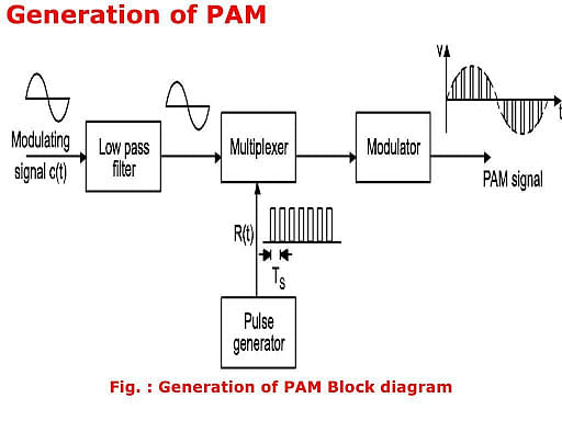
Pulse Amplitude Modulation Block Diagram
Modulation Techniques Used in Pulse Amplitude Modulation
In PAM, there are essentially three different modulation strategies that are used. They are as follows:
- Pulse Modulation - The signal is transmitted in pulses. They can take the shape of pulse width, Pulse Modulation, or a plain Pulse Amplitude format.
- Continuous Wave Modulation (CWM) - In this type of transmission, the message signal is modulated by the carrier signal. The fluctuation of amplitude, frequency, and phase change causes this transmission.
- Digital modulation - There are two forms of digital modulation. They can use pulse amplitude modulation or delta modulation to send data.
Read More:
Sampling Techniques in PAM
[Click Here for Sample Questions]
Sampling techniques in pulse amplitude modulation are:
- Flat top PAM- Every pulse's amplitude is proportional to the modulating signal's amplitude at the time of occurrence.
- Natural PAM- During the occurrence of a pulse, the amplitude is proportional to the modulating signal amplitude.
Also Read: Difference Between Analog and Digital Signal
Pulse Amplitude Modulation Application
[Click Here for Sample Questions]
Applications of Pulse amplitude modulation are:
- Broadband interface communication requires Ethernet connectivity.
- Microcontrollers are used to control signals.
- High-speed networking graphics card that reduces the noise-to-signal ratio.
- For the purpose of spectrofluorometric measurements during photosynthesis in Photo Biology
- LED drivers for energy-efficient lighting
- In Digital Televisions, for increased signal clarity and a crisper picture
Check out:
Pulse Amplitude Modulation Benefits
[Click Here for Sample Questions]
The advantages or benefits of Pulse amplitude modulation are:
- Amplitude signals can be transmitted and received very easily and quickly without being hampered by external circumstances.
- The PAM circuit is simple to build and operate.
- PAM can serve a dual purpose by transmitting messages and producing pulse signals at the same time.
- The Modulation and Demodulation processes are automated and do not require any manual intervention.
Also Read: Difference between AM and FM
Pulse Amplitude Modulation Drawbacks
[Click Here for Sample Questions]
The drawbacks of Pulse amplitude modulation are:
- The transmission of the PAM signal necessitates a bigger quantity of bandwidth.
- Additional noise remnants are created, which might cause disruptions.
- In many circumstances, it necessitates a higher volume of power usage.
- If Vestigial Side-band or Single and Double Sideband Suppressed Carrier (SSC) is utilized, all of these slight issues can be resolved or avoided entirely.
- Furthermore, Amplitude Modulation causes noise, which is one of the reasons why AM radio frequencies are not preferred over FM radio signals (FM).
For More PYQ Examples, Check:
Things to Remember
- Modulation refers to the superposition of low-frequency signals onto high-frequency carrier signals.
- Pulse amplitude modulation is used for the modulation of the signal transmission of the digital data.
- Pulse modulation is of two types: Analog modulation and Digital modulation.
- It is useful in Ethernet Communication.
- The transmission of the signal is done by the application of non-baseband.
- It is useful in LED lighting as it can be used as an electronic driver.
Sample Questions
Ques. TDM is used to multiplex five message signals, each at a frequency of 2 KHz. There are 256 quantization levels in use. Determine the system's transmission bandwidth. (2 marks)
Ans. Given that N = 5, fm = 2 KHz,
L = 256 levels then n = 8
We know that NR = 2fm
fs = NR = 2fm = 4 KHz
Bandwidth = Rb/2
= nNfs/2
= (8)(5)(4)
= 160 KHz
Ques. TDM multiplexes ten signals, each with a 2KHz band limit. The commutator takes 125 microseconds to complete one complete rotation. If a 5-bit encoder is used, determine the transmitter's bit rate. (2 marks)
Ans. Given that
N = 10, fm = 2 KHz, Ts = 125 microseconds
n = 5 bits/sample
fs = 1/Ts = 1/125x10-6 = 8 KHz
Bit rate Rb = nNfs = (5)(10)(8 KHz)
= 400 kbps
Ques. Five signals are multiplexed using TDM with fm = 5 kHz and no. of quantization levels are 256. Find the transmission bandwidth of the system. (3 marks)
Ans. Given N=5
fm=5 khz
2n = 256 that implies n=8
Nyquist rate fs=2fm
= 2*5 khz
= 10k
We know that bandwidth
BW = Rb/2
= nNfs/2
=8*5*10/2
= 200k
Ques. What is the limitation of using the pulse amplitude modulation method? (5 marks)
Ans. The drawbacks of Pulse Amplitude Modulation are:
- The transmission of the PAM signal necessitates a bigger quantity of bandwidth.
- Additional noise remnants are created, which might cause disruptions.
- In many circumstances, it necessitates a higher volume of power usage.
- If Vestigial Side-band or Single and Double Sideband Suppressed Carrier (SSC) is utilized, all of these slight issues can be resolved or avoided entirely.
- Furthermore, Amplitude Modulation causes noise, which is one of the reasons why AM radio frequencies are not preferred over FM radio signals (FM)
Ques. How can a Pulse Amplitude Modulation signal be detected? (1 mark)
Ans. A low-pass filter can be used to identify a PAM signal. A matching filter can be used to demodulate an FSK signal in a coherent manner. SNR for low-level signals increases when non-uniform quantization is used.
Ques. How is Pulse Amplitude Modulation generated? (1 mark)
Ans. A PAM is made up of a pure sine wave modulating signal, a square wave generator, and a PAM modulator circuit. The Wien Bridge Oscillator circuit is used to create a sine wave generator. This can result in a sine wave with less distortion at the output.
Ques. Why do we need to use Pulse Amplitude Modulation? (1 mark)
Ans. Pulse Amplitude Modulation (PAM) is a technique for transmitting analog signals using Pulse Stream. Furthermore, this facilitates the conversion of analog signals to digital signals. The best example is the ability to turn phone calls into video calls utilizing PAM.
Ques 8. What are the types of pulse modulation? (2 marks)
Ans. Pulse Amplitude Modulation (PAM), Pulse Position Modulation (PPM), Pulse Number Modulation (PNM), and Pulse Width Modulation are some of the most prevalent types of pulse modulation (PWM).
For Latest Updates on Upcoming Board Exams, Click Here: https://t.me/class_10_12_board_updates
Also Read:



Comments