



Content Writer
Commutator can be defined as an electrical rotary switch which enables the switching of current. It reverses the direction of current between the rotor and the electrical circuit.
- Commutator is in the form of a cylinder consisting of various metal segments rotating on the machine's armature.
- Two or more electrical contacts within the machine are called brushes.
- The commutator helps solve the problem of DC generators by converting AC current into DC current.
- An electrical switch is one of the electrical components which is responsible for breaking and closing an electrical circuit.
- DC circuits are the most commonly used switch in any electrical device.
- An electrical circuit is a form of closed loop which creates a network of electrical components where electrons can flow easily.
Read More: Physical Significance of Electric Field
Key Terms: Commutator, Electric Rotary Switch, DC Motors, DC Generators, AC Current, Electric Circuit, Force, Torque, Coil, Magnetic Field
What is a Commutator?
[Click Here for Sample Questions]
A commutator is a type of switch commonly employed in electronic appliances that changes the direction of current between the rotor and the electrical circuit. It belongs to the class of rotary switches run by electricity. Thus, they are rotary electrical switches.
- Commutator was discovered by William Ritchie and Hippolyte Pixii in 1832.
- It is used to divert the current periodically between two components, a rotor and an electrical circuit.
- Commutators are used chiefly with DC (Direct Current) machines such as DC generators, DC Motors, etc.
- When the direction of the current is changed within revolving windings every half turn, a steady revolving force (torque) gets created.
- In the case of a motor, the commutator applies electric current to the windings of the machine.
- On the other hand, in the case of a generator, the commutator picks off the current generated in the windings of the machine.
- The dielectric strength of the commutator ranges from 60 to 80 Volts.

Commutator
Read More:
Construction of a Commutator
[Click Here for Sample Questions]
Commutator is cylindrical in shape and changes the direction of current by the rotation of the coil winding inside. Every half rotation of the winding changes the direction of the flow of current.
- It is composed of several subunits and segments, which are made up of copper.
- A commutator is divided into several sections, and these sections are known as commutator segments.
- These segments are made up of conducting materials like copper, silver, etc.
- Commutator segments are also attached to the armature windings and metallic brushes.
- This, in turn, depends on the speed and voltage of the machine.
- In between the two segments, there is a layer of insulation which is made up of mica.
- Below the commutator, there is a laminated core that is composed of coiled circuits.
- The number of coils is half the number of commutator segments.
- The metallic brushes ensure good physical contact between the generator and the load.
- In the case of a motor, magnetic fields are applied in the direction of rotation of a device.
- On the other hand, in the case of a generator, mechanical torque is applied to maintain current in the device.
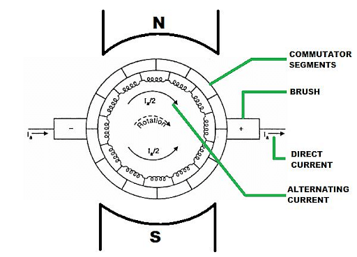
Construction of Commutator
Read More: Force of Attraction Formula
Working of a Commutator
[Click Here for Sample Questions]
The working of a commutator depends on the arrangement in which the shaft, commutator, and armature are winded together. Whenever the shaft rotates, the current flowing through the shaft is rotated by the commutator and is then transmitted to the armature. When a shaft completes half a rotation, the current is reversed.
- In the commutator, segments are attached to each other.
- They are pointed towards a revolving shaft in the electronic appliance.
- The commutator segments are also attached to the armature windings along with the metallic brush.
- It has two major functions, which include keeping the torque of the armature fixed and converting alternating current into direct current.
- The number of segments of the commutator is equal to the number of armature coils present.
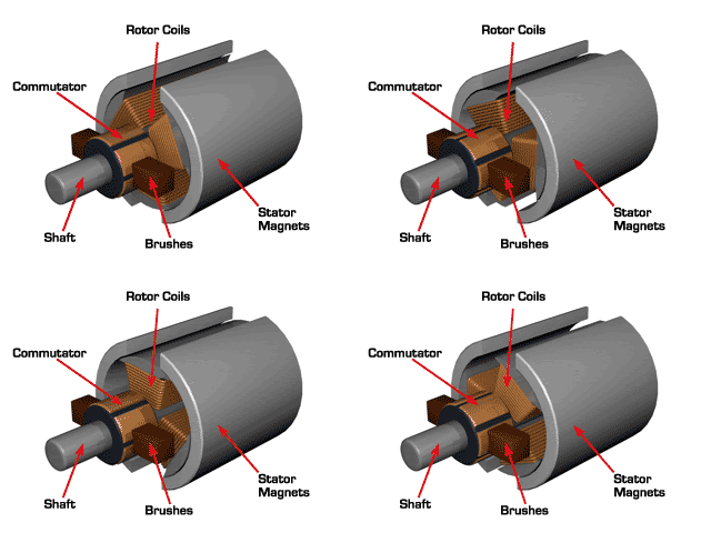
Working of Commutator
Read More: Lens Formula and Magnification
Commutation Process in DC Machine
[Click Here for Sample Questions]
The working of commutator in DC Machines are as follows:
- The metallic brushes in contact with the commutator are fixed and in contact with the magnet.
- The magnet provides a force for rotation, which ensures the voltage supply to the commutator segments and to the armature, too.
- When the commutator is rotating, the metallic brushes also come in contact with the insulator layer.
- At this point, the voltage flowing reaches the minimum level, i.e., zero.
- This, in turn, changes the electrical polarity in the coil.
- This polarity switch in the armature coils ensures the rotation of the armature coil in one direction.
- When the brush is in contact with both segments, the situation of neutral plane is created.
- If no neutral plane is produced, there are chances of high voltage flow and then spark and fire.
- The voltage generated in the commutator ranges from zero to maximum, but the polarity remains fixed.
- The rotation, position, and contact between the brush and the segments can be explained in five stages.

Commutator
Read More: Cells in Series and Parallel
Stages of Commutation in DC Machines
[Click Here for Sample Questions]
There are five stages of commutation in DC machines, which are as follows:
Stage 1
In stage 1, suppose there are two segments, segment A and segment B. The brush is in constant contact with the segments.
- The brush is in complete contact with one of the commutator segments, say segment A.
- On applying Kirchhoff’s law, we can easily calculate that the current flowing is 2I.
Stage 2
In stage 2, as the segment rotates, the brush moves from segment A to segment B. But most of the area is covered by segment A.
- In this, only one part of segment B is covered.
- On applying Kirchhoff’s law, we calculated that the current flowing is I/2 in both the segments.
Stage 3
In stage 3, the shaft is rotated further. The shaft is half in contact with segment A and half with segment B. The application of Kirchhoff’s current laws shows that the current from segment B is zero.
Stage 4
In stage 4, the operation performed in stage 2 is reversed. As a result, most of the area of segment B is covered.
- It leaves only a part of segment A.
- On applying Kirchhoff’s law, we calculated that the current flowing is I/2 in both the segments.
Stage 5
This is the last stage of commutation in DC machines. In this stage, the brush moves to the next segment, B, on complete rotation.
Read More: Differences Between Acceleration and Velocity
Functions of Commutator
[Click Here for Sample Questions]
The function of Commutator are as follows:
- It keeps the armature torque and MMF constant, and
- It converts Alternating Current into Direct Current, which also acts as a rectifier.
- A commutator is commonly used in DC appliances like DC Motors and DC Generators.
- In DC Motors, the commutator reverses the flow of the current with the rotation of the shaft and the armature tube.
- DC Motors maintains the flow of torque in one direction.
- In DC Generators, the electromagnetic field generated by the magnet inside the armature coil changes. Thus, the voltage generated and the type of current also change.
Read More:
Things to Remember
- Commutator is a type of switch commonly employed in electronic appliances
- Every half rotation of the winding changes the direction of the flow of current.
- This, in turn, creates a steady revolving force called torque.
- The working of a device depends on the arrangement in which the shaft, commutator, and armature are winded.
- The voltage generated in the commutator ranges from zero to maximum, but the polarity remains fixed.
- Commutator keeps the armature torque and MMF constant.
- It converts alternating current into direct current, which also acts as a rectifier.
Previous Years Questions
- Find current, i…...[KEAM 2018]
- The current II in the circuit shown is….[MHT CET 2015]
- A galvanometer has a resistance of 50ΩΩ. If a resistance of 1ΩΩ is connected across its terminals, the total current flow through the galvanometer is [IgIg represents the maximum current that can be passed through the galvanometer]...[DUET 2006]
- The potential difference between points AA and BB is:….
- The potential difference between AA and BB in the following figure is…...[KCET 2008]
- 4 cells each of emf2 V and internal resistance of 1O1O are connected in parallel to a load resistor of 2O2O . Then the current through the load resistor is….[KEAM]
- A circuit is made using R1,R2,R3,R4R1,R2,R3,R4 and a battery as shown in the following figure. Find the equivalent resistance of the given circuit and the current passing through R3….[KEAM]
- A battery of 6V6V and internal resistance 2Ω2Ω is connected to a silver voltameter. If the current of 1.5A1.5A flows through the circuit, the resistance of the voltameter is…..[KEAM]
- On increasing the temperature of a conductor. its resistance increases because the…..[KEAM]
- Two identical conductors maintained at different temperatures are given potential differences in the ratio 1 : 2. Then the ratio of their drift velocities is...[KEAM]
- An ammeter, voltmeter and a resistor are connected in series to a cell and the readings are noted as I and V . If another resistor R is connected in parallel with voltmeter, then[KEAM]
- A potentiometer wire, 10m10m long, has a resistance of 40Ω40Ω . It is connected in series with a resistance box and a 2V2V storage cell. If the potential gradient along the wire is (0.1mV/cm)(0.1mV/cm), the resistance unplugged in the box is...[KEAM]
Sample Questions
Ques. What is commutator? (2 marks)
Ans. Commutator is a type of electrical rotary switch commonly employed in electronic appliances. It is used to divert the current periodically between two components, a rotor and an electrical circuit. Thus, they alter and direct the change in the direction of the current. They change the direction of current by the rotation of the coil winding inside.
Ques. Explain the working of commutators. (2 marks)
Ans. The working of a commutator depends on the arrangement in which the shaft, commutator, and armature winded together. Whenever the shaft rotates, the current flowing through the shaft is rotated by the commutator and is then transmitted to the armature. When a shaft completes half a rotation, the current is reversed.
Ques. What are the functions of commutators? (2 marks)
Ans. Commutator has two major functions:
- It keeps the armature torque and MMF constant, and
- It converts Alternating Current into Direct Current, which also acts as a rectifier.
Ques. What are the components of a commutator? (2 marks)
Ans. The commutator is divided into several sections, and these sections are known as commutator segments. The commutator segments are also attached to the armature windings along with the metallic brush. These segments are made up of conducting materials like copper, silver, etc. In between the two segments, there is a layer of insulation. This layer of insulation is made up of mica.
Ques. What happens when the brush is in contact with two segments in the ratio of 1:3? (2 marks)
Ans. Once the shaft rotates, the brush is in contact with segment A, moves to the next segment B, and covers three fourth of segment B. Then 3/4th of the current comes from segment B, and 1/4th from segment A. Application of Kirchhoff’s current laws show that the current from segment a and b is I/2
Ques. How does the commutator work in a DC Motor and a DC Generator? (3 marks)
Ans. Here, the commutator reverses the flow of the current with the rotation of the shaft and the armature tube. It maintains the flow of torque in one direction and converts AC to DC.
- In DC generations, the electromagnetic field generated by the magnet inside the armature coil changes.
- Thus, the voltage generated and the type of current also change.
- The commutator keeps the flow of current unidirectional and in DC form.
Ques. What is the neutral plane? (2 marks)
Ans. When the brush moves from one segment to another, there is a point where the brush is in contact with both segments; at this point, the situation is called the neutral plane. If no neutral plane is produced, there are chances of high voltage flow and then spark and fire.
Ques. What are the uses of commutators? (3 marks)
Ans. The various uses of commutators are as follows:
- Commutators are used to supply power to rotors installed inside a motor.
- They are used in electronic appliances at homes, such as vacuum cleaners, drilling machines and other lightweight appliances.
- Commutators are responsible for keeping the flow of current unidirectional in DC Generators.
- It will reverse the direction of current inside a motor and supply that current to armature conductors.
Ques. What are the disadvantages of using a commutator? (5 marks)
Ans. The disadvantages of using a commutator are as follows:
- The sliding friction generated between the brushes and commutators consumes a large amount of energy, which is low in the case of a machine,
- The segments of copper and brushes wear down due to continuous generation of friction, which will create a large amount of dust. So these types of machines only run for a short period of time.
- The resistance between the brush and commutator creates a voltage drop called voltage drop, which causes a large amount of power loss.
- Large-size direct current machines cannot be built with the use of commutators.
- Commutators are used to switch currents in machines, which can sometimes cause sparking at the contacts.
Ques. What is the difference between a DC Motor and DC Generator? (4 marks)
Ans. The difference between DC Motor and DC Generator are as follows:
| DC Motor | DC Generator |
|---|---|
| DC Motor is a device which converts electrical energy to mechanical energy. | DC Generator is a device which converts mechanical energy into electrical energy. |
| It is based on the Fleming left hand rule. | It is based on the Fleming right hand rule. |
| In this current is supplied to the armature winding. | In this current is produced in the armature winding. |
| For example: ceiling fan and cars | For example: power stations |
Ques. What are two types of laboratory commutators? (2 marks)
Ans. The two types of laboratory commutators are as follows:
- Ruhmkorff Commutator: It is a type of commutator that is used in motors and dynamos. The device is constructed using brass and ivory segments.
- Pohl Commutator: It is a type of commutator used in blocks of ebonite connected by copper wires. The pair of copper wires are dipped into one or other pairs of mercury wells.
Ques. Explain (A) Rotary Switch (B) Rotary Transformer (C)Slip Ring (3 marks)
Ans. (A) Rotary Switch: A Rotary Switch is a switch that is being used when more than two positions are needed for a device. It is used as a channel selector on television receivers with multiple channel frequencies.
(B) Rotary Transformer: A rotary transformer is a device that is used to combine the electrical signals that are rotating in relation to each other. They are mainly used in videocassette recorders.
(C)Slip Ring: Slip rings are electronic devices that are used to maintain electrical circuits between a rotating and static structure. It is used to improve the mechanical power of a device.
Ques. A commutator having a diameter of 30 cm rotating at 400 rpm. If the time of commutation of commutator is 1.5 msec, the value of brush width will be ____ cm? (3 marks)
Ans. Given, Speed of rotation = 400 rpm
- 400 / 60=20 / 3 revolution/sec
- Peripheral velocity of commutator, Vp=πDN
- π × 30 × 20 / 3cm/sec = 200 π cm/sec
- Also, Vp × tc = Brush width
- Brush width = 200π × 1.5 × 10− 3
- 0.942 cm
Ques. A commutator with a diameter of 50 cm rotates at 360 rpm. For a brush width of 2 cm, the time of commutation is? (3 marks)
Ans. Rotation speed = 360 rpm
- N=360 / 60 = 6 rev / sec
- Peripheral velocity of commutator, Vp=πDN
- π × 50 × 6 cm/sec
- 300π cm/sec
- Also, Vp × tc = Brush width
- Time of commutation, tc = 2 / π × 50 × 6 = 0.002 msec
Ques. A disc of mass 2 kg and diameter 2m is performing rotational motion. Find the work done, if the disc is rotating from 600rpm to 1200rpm? (3 marks)
Ans. As we know I=mR2 / 2 =1kg/m2
- ωi=600 × 2π / 60 = 20π
- ωf=1200 × 2π / 60 = 40π
- ΔKE = 1 / 2 [I (ωf)2− I (ωi)2]
- I / 2 ((40π)2−(20π)2)
- 2 x 600 π2 = 11835 J
Check-Out:



Comments