



Content Curator
Difference between Series and Parallel circuit is the amount of current that can flow through each of the elements inside the circuit. A series connection is an electric circuit that contains a connection of circuits in a series combination. A parallel connection is a circuit where starting points of all the components are connected to one common point.
The voltage across components in a parallel circuit is the same. The total current is the sum of the currents flowing through each component. In the series circuit, all the components are in a single circuit; thus, if one bulb burns out in a series circuit, the entire circuit is broken.
| Table of Contents |
Key Terms: Series Circuit, Parallel Circuit, Resistors in Series, Series Connection, Resistors in Parallel
What is Circuit?
[Click Here for Sample Questions]
An electrical circuit is a closed system in which a conductor is connected to a power source's positive and negative terminals. There is a switch that allows the passage of electric current via the circuits to be disconnected. A resistor can be used to control the flow of electric current in an electrical circuit. It can also be used to control a light bulb, a motor, or any other electronic device. The type of electric circuit is determined by the connections placed in it.
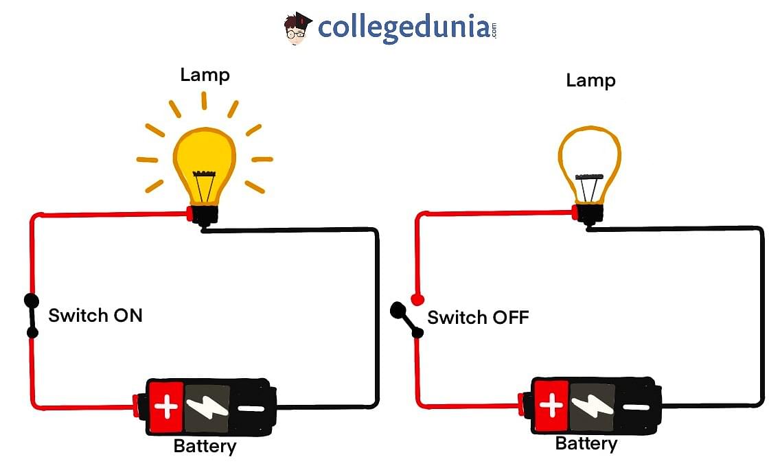
Circuit
The two types of circuit connections are:
- Series connection
- Parallel connection
The video below explains this:
Types of Circuits Detailed Video Explanation:
What is Series Circuit?
[Click Here for Previous Year Questions]
A series connection is an electric circuit in which the circuit's elements are linked one by one. It signifies that the end of one element in the circuit will link to the beginning of another.
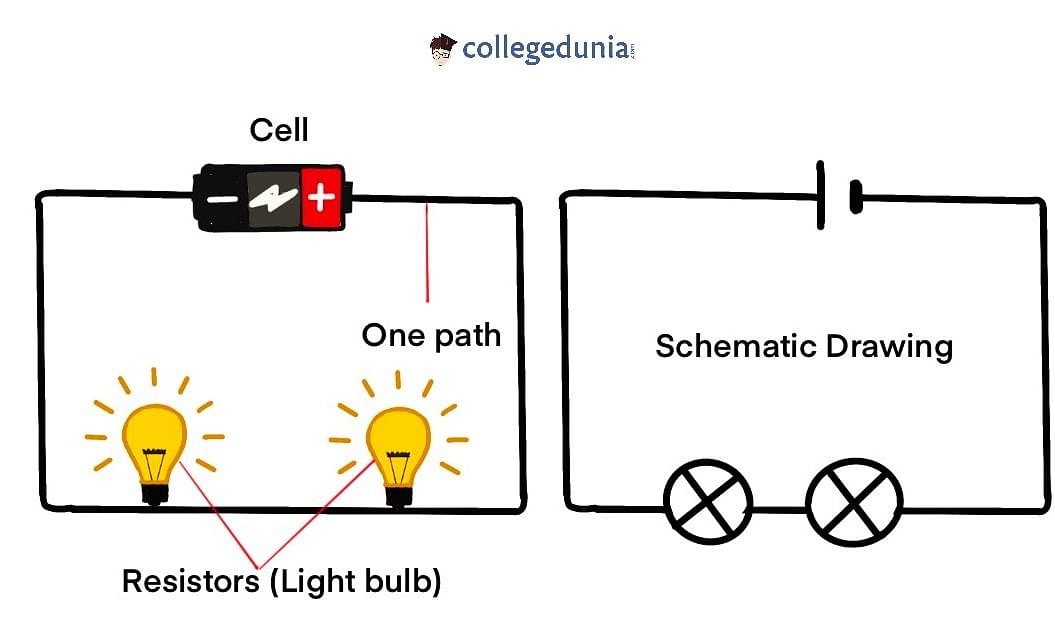
Series Circuit
Let's simplify this concept a little. The same current will flow through all of the circuit's components or elements in this circuit design. A circuit will not be formed from the current.
Consider a series circuit as a set of decorative string lights for the home. This is nothing more than a string of small lights connected in a series. If one bulb in a series burns out, the rest of the bulbs in the series will not light up.
What is Parallel Circuit?
[Click Here for Sample Questions]
A parallel connection is an electric circuit in which all of the electrical components' starting points are connected at the same time. Similarly, the components' endpoints will be joined at a specific moment.
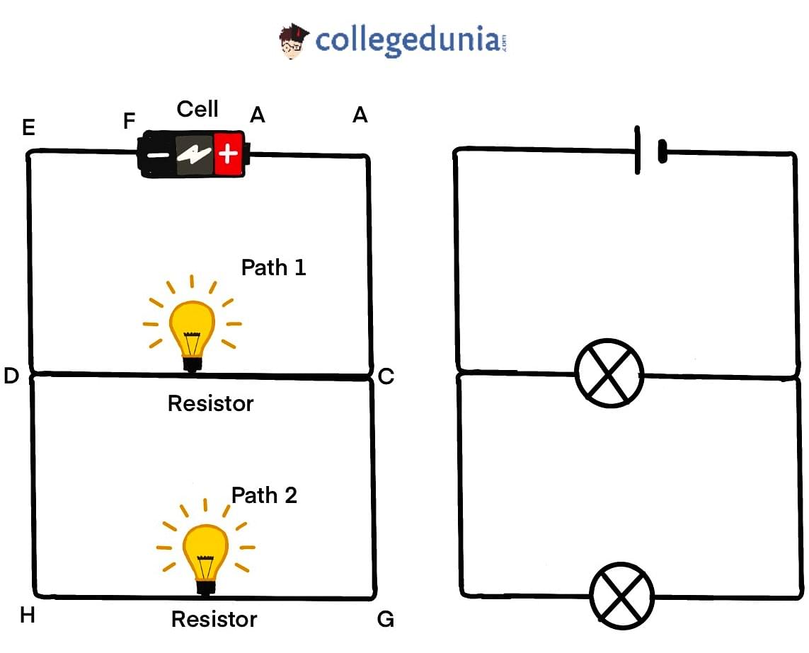
Parallel Circuit
Simply said, the amount of power delivered is divided by the total number of branches that emerge from a location in a parallel connection. When an electric current flows along many pathways, the circuit is said to be parallel. The components in parallel circuits will have a constant voltage across all of their ends.
Difference between Series and Parallel Circuit
[Click Here for Previous Year Questions]
The major difference between the two circuits (series and parallel) is the amount of current that flows through each of the components in the circuit. In a series circuit, the same amount of current flows through all the components that are placed in it while in parallel circuits, the components are placed in parallel with each other because of which the current flow gets split.

Difference between Series and Parallel Circuit
This is one of the differences between the two circuits. The other differences are discussed below:
| Mass | Volume |
|---|---|
| The current passing through each component combines to generate the source's current flow. | All of the components receive the same amount of current. |
| When resistors are connected in parallel, the voltage across each resistance is the same. The polarities are also the same. | When resistors are connected in a series circuit, the voltage across each resistor varies, even though the current flow through all of them is the same. |
| Components in an electrical circuit are placed in a parallel configuration. | Components in an electrical circuit are organized in a line. |
| Even if one component fails, the others will continue to work because each has its own circuit. | If a single component fails, the entire circuit will burn out. |
| If V is the total voltage, then V1=V2=V3 is the formula. | The total voltage is equal to V1+V2+V3. |
Things to Remember
- An electrical circuit is a closed system in which a conductor is connected to a power source's positive and negative terminals.
- The two types of circuit connections are: Series connection and Parallel connection.
- In the series circuit, all the components in a single circuit due to which if one bulb burns out in a series circuit, the entire circuit is broken.
- A parallel connection is an electric circuit in which all of the electrical components' starting points are connected at the same time.
Previous Year Questions
- What is the value of inductance L for which the current is… [NEET 2007]
- A series LCR circuit resonates at 10 kHZ… [WBJEE 2016]
- In a circuit L, C and R are connected in series with an alternating… [BITSAT 2005]
- For given L-R circuit, growth of current as function of time t is shown in… [UPSEE 2017]
- The time constant of C-R circuit is… [NEET 1992]
- A capacitor of capacitance ′C′, is connected across an ac source of… [WBJEE 2021]
- An LCR series circuit containing a resistance of 120Ω has angular resonance… [WBJEE 2009]
- An AC generator producing 10V(rms) at 200 rad/s is connected in… [TS EAMCET 2017]
- The power factor of R-L circuit is… [KCET 2020]
- The power factor of LCR circuit at resonance is… [KEAM]
Sample Questions
Ques. What is the significance of the term "parallel circuit"? (2 marks)
Ans- A parallel circuit is formed when the components in a circuit are connected in a parallel manner. If you look attentively at the diagram, you'll notice how these components are connected in a parallel manner.
Ques. What is the formula for calculating the overall resistance of a series circuit? (1 mark)
Ans- In a series circuit, the total resistance equals the sum of the individual resistances.
Ques. How are batteries generally connected? (1 mark)
Ans- The batteries are generally connected in series.
Ques. Is series or parallel connection cost-efficient? (1 mark)
Ans- Series connection is more cost-efficient.
Ques. Which device measures voltage? (1 mark)
Ans- Voltmeter is used to measure voltage.
Ques. Define circuit. What are the two types of circuit connections? (3 marks)
Ans- An electrical circuit is a closed system in which a conductor is connected to a power source's positive and negative terminals. There is a switch that allows the passage of electric current via the circuits to be disconnected. A resistor can be used to control the flow of electric current in an electrical circuit. It can also be used to control a light bulb, a motor, or any other electronic device. The type of electric circuit is determined by the connections placed in it.
The two types of circuit connections are:
- Series connection
- Parallel connection
Ques. What is series circuit? (2 marks)
Ans- A series connection is an electric circuit in which the circuit's elements are linked one by one. It signifies that the end of one element in the circuit will link to the beginning of another. Let's simplify this concept a little. The same current will flow through all of the circuit's components or elements in this circuit design. A circuit will not be formed from the current. Consider a series circuit as a set of decorative string lights for the home. This is nothing more than a string of small lights connected in a series. If one bulb in a series burns out, the rest of the bulbs in the series will not light up.
Ques. What is meant by parallel circuit? (2 marks)
Ans- A parallel connection is an electric circuit in which all of the electrical components' starting points are connected at the same time. Similarly, the components' endpoints will be joined at a specific moment. Simply said, the amount of power delivered is divided by the total number of branches that emerge from a location in a parallel connection. When an electric current flows along many pathways, the circuit is said to be parallel. The components in parallel circuits will have a constant voltage across all of their ends.
Ques. How is total resistance of any series circuit calculated? (1 mark)
Ans- Total resistance in a series circuit is equivalent to the sum of the individual resistances.
Ques. Differentiate between series and parallel circuit. (4 marks)
Ans-
| Mass | Volume |
|---|---|
| The current passing through each component combines to generate the source's current flow. | All of the components receive the same amount of current. |
| When resistors are connected in parallel, the voltage across each resistance is the same. The polarities are also the same. | When resistors are connected in a series circuit, the voltage across each resistor varies, even though the current flow through all of them is the same. |
| Components in an electrical circuit are placed in a parallel configuration. | Components in an electrical circuit are organized in a line. |
| Even if one component fails, the others will continue to work because each has its own circuit. | If a single component fails, the entire circuit will burn out. |
| If V is the total voltage, then V1=V2=V3 is the formula. | The total voltage is equal to V1+V2+V3. |
Ques. Draw schematic diagrams of an electric circuit comprising 3 cells and an electric bulb, ammeter, plug-key in the ON mode and another with same components but with two bulbs in parallel and a voltmeter across the combination. (2012) (3 Marks)
Ans-

Ques. A set of three bulbs each having power P are connected in series in an electric circuit. In another circuit, another set of three bulbs of same power are connected in parallel to the same source. Answer the following:
(i) Will the bulbs in both the circuits glow with the same brightness? Justify your answer.
(ii) Now if one bulb in each circuit get fused. Will the rest of the bulbs continue to glow in each circuit? Explain why.
(iii) Draw circuit diagram for each case representing each bulb by a resistor. (2012) (5 Marks)
Ans-
(i) Bulbs in parallel provide more brightness because:
(a) each bulb gets same voltage which is equivalent to the applied voltage.
(b) each bulb draws required current from the mains (source). Therefore, they work properly.
(ii) When one bulb in each circuit get fused,
Rest of the bulbs in series will not glow because in series arrangement, there is only a single path for the flow of current.
Whereas, in parallel, rest of the bulbs will continue to glow as in parallel connection:
(a) individual branch in the circuit completes its own circuit, or
(b) different paths are available for the flow of current.
(iii) Circuit diagram

Also Read:



Comments