



Content Curator
The difference between ammeter and voltmeter is that an ammeter measures the current flowing through a circuit while a voltmeter measures the potential difference.
- In an electric circuit, a voltmeter is connected in parallel whereas an ammeter is connected in series.
- The connection polarity of both of these devices is the same.
- The negative terminal is connected with the negative polarity and the positive terminal is connected with the positive polarity of the supply.
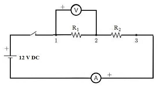
Connection of Voltmeter and Ammeter in a Circuit
Discover about the Chapter video:
Current Electricity Detailed Video Explanation:
Read More: Difference between Ammeter and Voltmeter
Very Short Answer Questions (1 Mark Questions)
Ques. What is an ammeter?
Ans. An ammeter is a device used to measure the value of current flowing in a circuit. It is always connected in series with the circuit.
Ques. What is a voltmeter?
Ans. A voltmeter is a device that is connected in parallel with a circuit and measures the potential difference applied across two ends of the circuit.
Ques. What is a differential voltmeter?
Ans. The differential voltmeter is one that is used to measure the voltage difference between a known and an unknown source. It is also called a ‘Potentiometer Voltmeter’ since its working principle is similar to that of the potentiometer.
Ques. How can a galvanometer be converted into an ammeter?
Ans. To convert a galvanometer into an ammeter, a low resistance called a ‘shunt’ is connected in parallel to the galvanometer. This reduces the resistance offered by the galvanometer and thus the current flowing through it can be measured.
Ques. A current of 300 mA is made to flow through a 6 kΩ resistor. What is the potential difference across the resistor?
Ans. According to Ohm’s law, V = IR
I = 300 mA = 0.3 A and R = 6 kΩ = 6000 Ω
So, V = 0.3 x 6000 = 1800 V
Ques. Define current electricity.
Ans. The flow of charged particles such as electrons and ions from one part of the circuit to another part is called current electricity.
Short Answer Questions (2 Marks Questions)
Ques. What are the different types of voltmeters?
Ans. Depending upon their construction, voltmeters are of the following types:
- Permanent Magnet Moving Coil Voltmeter
- Moving Iron Voltmeter
- Electro Dynamometer Type Voltmeter
- Rectifier Type Voltmeter
- Induction Type Voltmeter
- Electrostatic Type Voltmeter
- Digital Voltmeter
Ques. Name the different types of ammeter.
Ans. Based on their construction, the different types of ammeters are:
- Permanent Moving Coil Ammeter
- Moving Iron Ammeter
- Electro-dynamometer ammeter
- Rectifier-type Ammeter
Ques. What is the difference between DC Voltmeter and AC Voltmeter?
Ans. The DC voltmeter measures the DC voltage while the AC voltmeter measures the AC voltage. In a DC voltmeter, the peak value of DC voltage is measured whereas an AC voltmeter measures the RMS value of AC voltage.
Ques. What will happen if a voltmeter is connected in series with a circuit?
Ans. The resistance of a voltmeter is very high. If it is connected in series with the circuit, then it will draw a large amount of current from it and will not give accurate readings of voltage. That is why a voltmeter is always connected in parallel so that it allows the flow of the current through the circuit. The resistance of an ideal voltmeter is infinite to ensure that the current drawn by it is negligible.
Ques. What will happen if an ammeter is connected in parallel with a circuit?
Ans. An ammeter is always connected in series with the circuit because:
- It offers very low resistance to the current, thus it measures the accurate value of the current by allowing it to pass through it completely.
- If it is connected in parallel, it might cause a short circuit and damage the device.
Ques. Two resistors of resistance 3 Ω each are connected in series with a 12 V battery. Find the current flowing through each resistor.
Ans. Since the two resistors are connected in series, therefore equivalent resistance of the circuit is
Req = R1 + R2 = 3 + 3 = 6 Ω
Using Ohm’s law, V = IR, we have
Current flowing through the circuit, I = V/R
⇒ I = 12/6 = 2A
Hence, current of 2 A is flowing through each resistor.
Check Also:
Long Answer Questions (3 Marks Questions)
Ques. What are the readings of the voltmeter and ammeter in the following circuit?
Ans. In the above diagram, the net resistance of the resistors connected in parallel is,
1/RP = 1/100 + 1/100
1/RP = 2/100 = 1/50
RP = 50
This is connected in series with another resistor of 100, therefore the net resistance is:
Req = 100 + 50
Req = 150
I = V/R
I = 6/150
I = 0.04 A (Reading of Ammeter)
Now, V = IR
V = 0.04 100
V = 4 V (Reading of Voltmeter)
Ques. Find the reading of the voltmeter in the circuit given below.
Ans. In the circuit shown above, the net resistance is,
Req = 300
I = V / Req
I = 30 / 300 = 0.1 A
Now, reading of voltmeter (V) = IR
V = 0.1 125
V = 12.5 V
Ques. What is the reading of the ammeter in the circuit given below?
Ans. In the above circuit, the effective resistance is,
Reff = 10 + 20/3 + 5
Reff = 65/3
I = V/Reff
I = (5 3) / 65
I = 3/13 A
Ques. What are the key differences between an ammeter and a voltmeter?
Ans. The key differences between an ammeter and a voltmeter are tabulated below:
| Ammeter | Voltmeter |
|---|---|
| It is a device used to measure the current in a circuit. | It is used to measure the potential difference applied across a circuit. |
| Its resistance is low. | It has a very high resistance. |
| It is always connected in series with the circuit. | It is always connected in parallel with the circuit. |
| For an ideal ammeter, the resistance is 0. | For an ideal voltmeter, the resistance is infinite. |
| In an ammeter, the range cannot be changed. | The range can be changed in a voltmeter. |
Very Long Answer Questions (5 Marks Questions)
Ques. In the circuit, R1 = 400 and R2 = 200. If the resistance of the voltmeter is 10,000, then find the reading of the voltmeter.
Ans. Here, the equivalent resistance is,
Req = 400 + (200 10000) / (200 + 10000)
Req = 400 + 196 = 596
I = V/R = 6/596 A
The potential across R1 is given by,
V1 = IR1
V1 = 6/596 400
V1 = 4.026 V
The potential across R2 is given by,
V2 = 6 - 4.026
V2 = 1.974 V
Hence, the reading of the voltmeter = 1.97 V
Ques. In the circuit given below, the variable resistor X is adjusted so that high resistance voltmeter V shows a reading of 1 V. Find the resistance.
Ans. In the upper part (through 5V voltage),
VA + 2i - 5 = VB (i = current through the circuit)
Now, VA - VB = 5 - 2i = 1
i = (5 - 1) / 2
i = 2 A
In the lower part (through 2V voltage),
VA + 2 - iX = VB
iX = VA - VB + 2
But, VA - VB = 1 V, and i = 2 A
So, X = (1 + 2) / 2
X = 1.5
Ques. Find the reading of the ammeter in the circuit given below.
Ans. The distribution of current in the circuit is as follows:
Here, I1 = 4.5/9 = 0.5 A
The resistors (9, 3) and 6 are in parallel, so
4.5 + 3I1 = 6I2
4.5 + 3(0.5) = 6I2
I2 = (4.5 + 1.5) / 6
I2 = 1 A
I = I1 + I2 = 0.5 + 1 = 1.5 A
Equivalent resistance between C and D (RCD) = (1/10 + 1/12 + 1/15)-1 = 4
Potential across C and D (VCD) = IRCD = 1.5 4 = 6V
The potential across A and D is,
VAD = VAB + VBC + VCD
VAD = 6I2 + 2I + 6
VAD = 6(1) + 2(1.5) + 6
VAD = 6 + 3 + 6 = 15 V
Since 20 is connected in parallel across total resistance across A and D, so this will be the potential across 20 as well as the voltmeter.
Thus, I4 = 15/20 = 0.75 A
Reading in the ammeter = I + I4 = 1.5 + 0.75 = 2.25 A
For Latest Updates on Upcoming Board Exams, Click Here: https://t.me/class_10_12_board_updates
Check-Out:



Comments