



Education Content Expert
Induced Voltage is an electric potential that is created by an electric field, magnetic field, or current. The induced voltage is produced as a result of electromagnetic induction. Electromagnetic induction is a process in which a conductor is placed in a certain position and the magnetic field remains stationary or varies as the conductor moves. It results in the production of a voltage or electromotive force across the electrical conductor known as the induced voltage. Induced Voltage can be explained with the help of Faraday’s law of induction.
Induced Voltage Formula is given as ε = N x dΦ/dt, where, ε denotes the induced voltage, N refers to the number of turns in the coil, dΦ is the magnetic flux and dt refers to the time taken. Induced Voltage Formula is also described as the relation between induced voltage and the magnetic flux.
Key Terms: Induced Voltage, Electromagnetic Induction, Magnetic Flux, Induced Voltage Formula, Faraday’s Law of Induction
What is Induced Voltage?
[Click Here for Sample Questions]
Induced Voltage of a closed circuit is defined as the rate of change of magnetic flux through that closed circuit. Electromagnetic Induction plays a crucial role in the production of the induced voltage. It is the procedure of producing emf (induced voltage) by exposing a conductor to a magnetic field.
- Induced Voltage is described using Faraday’s law of induction.
- Induced Voltage is directly proportional to the number of turns in the coil, magnetic field, and cross-section of the loop.
- It changes inversely with an increase in time.
- Induced Voltage is denoted by the symbol ε.
- The SI Unit of Induced Voltage is volts (V).
- The dimensional formula of induced voltage is [M1L2A−1T−3].
- Induced voltage in natural and man-made materials is planned carefully in various disciplines with all safety and equipment protection.
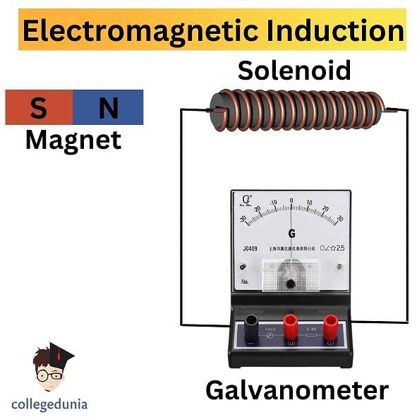
Electromagnetic Induction
Induced Voltage Formula
[Click Here for Previous Years' Questions]
Induced Voltage Formula is given as follows:
ε = N × dΦ/dt
Where
- ε refers to the induced voltage.
- N refers to the number of turns in the coil.
- dΦ refers to the magnetic flux.
- dt refers to the time taken.
Induced Voltage Formula is also termed as the relation between induced voltage and the magnetic flux.
Read More: Magnetic Flux Formula
In terms of the magnetic field across the conductor and its area, the induced voltage formula is expressed as:
ε = NBA/t
Where
- ε denotes the induced voltage.
- N refers to the number of turns in the coil.
- B is the magnetic field.
- A is the area of the coil.
- t is the time taken.
Induced Voltage Solved ExamplesExample 1: Determine the induced voltage of a coil of 10 turns if the flux is given as 2 Tm2 for 5 s. Solution: According to the question,
Using the Induced Voltage Formula, ε = N × dΦ/dt ε = 10 × 2/5 = 4 V Thus, the induced voltage of the coil is 4V. Example 2: Calculate the flux if the induced voltage of a coil of 12 turns is given as 7 V for 10 s. Solution: According to the question,
Using the Induced Voltage Formula, ε = N × dΦ/dt Rearranging the formula, dΦ = ε dt/N dΦ = 7 (10/12) = 5.83 Tm2 Thus, the flux is calculated as 5.83 Tm2. |
Things to Remember
- Induced Voltage is the voltage induced in the conductor by a changing magnetic field due to electromagnetic induction.
- It is represented by the symbol ε and its SI unit is Volts (V).
- The concept of induced voltage is described with the help of electromagnetic induction.
- Induced Voltage Formula is ε = N × dΦ/dt. Here, N is the number of turns in the coil, dΦ is the magnetic flux and dt is the time taken.
- Induced Voltage Formula also illustrates the relation between induced voltage and the magnetic flux.
Previous Years’ Questions (PYQs)
- A step-up transformer raises the voltage from 220V to 11000V…
- In an ideal transformer, the voltage and the current in the primary… (KCET 1998)
- The effective resistance across the points A and I is… (KEAM)
- In a coil of resistance 100Ω, a current is induced by changing… (JEE Main 2017)
- Magnetic energy density in an inductor is given by… (JKCET 2018)
- The primary winding of a transformer has 500 turns whereas… (NEET 1997)
- A circular loop of radius 0.3 cm lies parallel to a much bigger… (JEE Main 2013)
- A battery of e.m.f 10 V and internal resistance 0.5… (NEET 1992)
- The statement "Polarity of induced emf is such that it tends to… (J & K CET 2011)
- The polarity of induced emf is given by… (KEAM)
Sample Questions
Ques. Calculate the induced voltage of a coil of 5 turns if flux is given as 2.5 Tm2 for 3 s. (3 Marks)
Ans. Given parameters are:
- N = 5
- dΦ = 2.5
- dt = 3
Using the Induced Voltage Formula,
ε = N × dΦ/dt
ε = 10 × 2.5/3
ε = 25/3
ε = 8.33 V
Thus, the induced voltage is 8.33 V.
Ques. What will be the induced voltage of a coil if the flux is 6 Tm2 for 5 s? The number of turns in the coil is given as 8. (3 Marks)
Ans. According to the question,
- N = 8
- dΦ = 6
- dt = 5
Using the Induced Voltage Formula,
ε = N × dΦ/dt
ε = 8 × 6/5
ε = 48/5
ε = 9.6 V
Thus, the induced voltage is calculated as 9.6 V.
Ques. Explain the first and the second law of electromagnetic induction. (3 Marks)
Ans. The first and the second law of electromagnetic induction are as follows:
- First Law of Electromagnetic Induction: According to the first law, whenever a conductor is placed in a varying magnetic field, emf induces, and this emf is referred to as an induced EMF. In case it is a conductor is a closed circuit then the induced current flows through it.
- Second Law of Electromagnetic Induction: According to the second law, the magnitude of the induced EMF is equal to the rate of change of flux linkages.
Ques. Calculate the induced voltage of a coil of 12 turns if flux is given as 5 Tm2 for 10 s. (3 Marks)
Ans. According to the question,
- N = 12
- Φ = 5
- t = 10
Using the Induced Voltage Formula,
ε = N × dΦ/dt
ε = 12 × 5/10
ε = 6 V
Thus, the induced voltage is 6 V.
Ques. What will be the flux if the induced voltage of a coil of 7 turns is 9 V for 8 s? (3 Marks)
Ans. Given parameters are:
- ε = 9
- N = 7
- dt = 8
Using the Induced Voltage Formula,
ε = N × dΦ/dt
On rearranging it,
dΦ = ε dt/N
dΦ = 9 (8/7)
dΦ = 10.28 Tm2
Thus, the flux is 10.28 Tm2.
Ques. What is electromagnetic induction? (3 Marks)
Ans. Electromagnetic Induction is defined as the induction of an electromotive force by the motion of a conductor across a magnetic field or by a change in magnetic flux in a magnetic field. The process takes place when a conductor is set in a moving magnetic field or when a conductor is always moving in a stationary magnetic field. Electromagnetic induction is a very wide concept and is used in generators, inductors, motors, and transformers. The magnetic flow meter is based on the concept of electromagnetic induction only.
Ques. What will be the number of turns if flux is 2.93 Tm2, and the induced voltage is 11 V for 4 s? (3 Marks)
Ans. According to the question,
- ε = 11
- dΦ = 2.93
- dt = 4
Using the Induced Voltage Formula,
ε = N × dΦ/dt
Rearranging the formula, we get
N = ε dΦ/dt
N = 11 (2.93/4)
N = 8 turns
Thus, the number of turns in the coil is 8.
Ques. List the factors affecting induced voltage. (3 Marks)
Ans. As long as there is motion between the field and the conductor, a voltage could be induced. The three factors that affect the size of the voltage are:
- Size of the magnetic field.
- Active length of the conductor.
- Speed at which the conductor passes through the field.
Ques. What will be the induced voltage if the number of turns is 7, the magnetic field is 12 T, the cross-section area is 10 sq. m and the time is given as 5 s? (3 Marks)
Ans. Given that,
- B = 12
- A = 10
- N = 7
- dt = 5
First we have to calculate the magnetic flux,
dΦ = BA
dΦ = 12 (10)
dΦ = 120 Tm2
Now, Using the Induced Voltage Formula,
ε = N × dΦ/dt
ε = 7 (120/5)
ε = 168 V
Thus, the induced voltage of the coil is 168 V.
Ques. Give a reason why induced emf is negative. (2 Marks)
Ans. The emf induced in an electric circuit always acts in such a direction that the current it drives around the circuit is opposite to the change in magnetic flux that produces the emf. The (-ve) or minus sign reminds us that the emf always acts to oppose the change in magnetic flux which generates the emf.
Check-Out:



Comments