



Education Journalist | Study Abroad Lead
Varactor refers to the variable reactance. In this diode, as we change the applied reverse bias voltage, its capacitance or in other words its reactance will change. Particularly when we want to change the capacitance in the circuit using the external applied voltage, then these varactor diodes are very useful. Because of this property, they are used in RF communication systems.
| Table of Content |
Key Takeaways: Varactor, Varicap, Diode, Reverse bias, Capacitance, Voltage, Circuit, Communication system
Basics of Varactor diode
[Click Here for Sample Questions]
Varactor diodes are the type of pn junction diodes whose internal capacitance can be changed by applying the reverse bias voltage. So these diodes are also known as the varicap diodes.
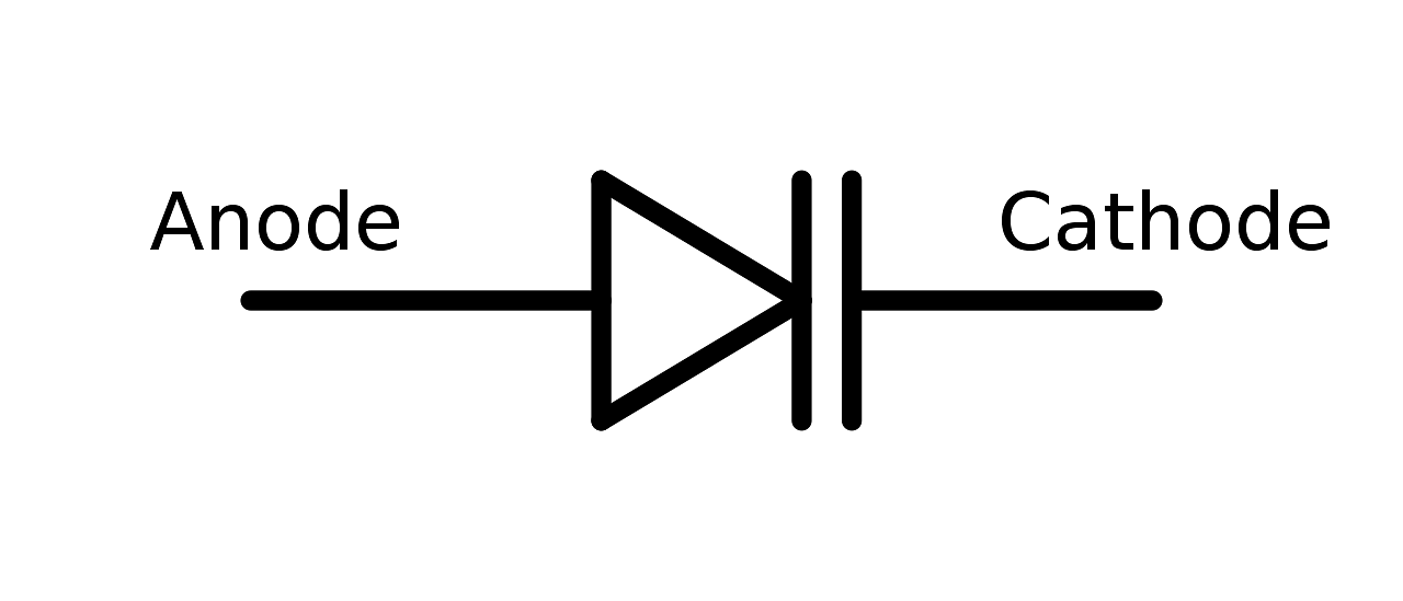
Symbol of a Varactor Diode
The symbol indicates that it is the pn junction but unlike the normal rectifier diode, it is intended to be used as a capacitor. Let’s see how we can change the capacitance of the parallel plate capacitor. So for a parallel plate capacitance can be given as
C = εA/d
A → Area of the plates
ε → Permittivity of the dielectric material
d → Distance between two plates or the thickness of the dielectric material.
For the fixed value of Permittivity and area A, if we change the distance between the two plates or in other words, if we change the thickness or gap of the dielectric medium then the capacitance of the capacitor will also change. So, with the same concept, the capacitance of a varactor diode is varied.
The video below explains this:
Varactor diode Detailed Video Explanation:
Also Read:
| Related Articles | ||
|---|---|---|
| Junction Transistor | Digital Electronics and Logic Gates | Extrinsic Semiconductors |
| Intrinsic Semiconductors | Bridge Rectifier | Application of Junction Diode |
Structure of Varactor Diode
[Click Here for Sample Questions]
Varactor diode is a PN junction diode, at the P side there is a hole and at the N side there are electrons. Positively charged at holes and negatively charged at electrons. Therefore, the depletion region width is W, Both holes and electrons are pushed away from the depletion region because the width of the depletion region increases. When we apply reverse bias in the pn junction the depletion region increases.

Structure of Varactor Diode
Working Principle
[Click Here for Sample Questions]
The width of the depletion region increases as the reverse bias voltage across the pn junction also increases.
Here in the case of varactor diode-
P and N region are analogous to conducting plates of the capacitor
As we increase the reverse voltage the depletion region (Dielectric) width also increases.
C α 1/ W
Here capacitance is inversely proportional to the width of the depletion region (Dielectric) and the capacitance decreases.
W → Width of depletion region (Dielectric)
We can say that
CT α 1/W
CT – Junction capacitance or transition capacitance is inversely proportional to the width of the depletion region.
Transition capacitance varies inversely with the reverse voltage.
By varying the reverse voltage it is easy to control the capacitance of the junction so that the varactor diode is the variable capacitor diode.
As we increase the reverse voltage the capacitance goes down. So the capacitance is inversely proportional to the reverse voltage in the case of a varactor diode.
Applications of Varactor Diode
[Click Here for Sample Questions]
These are the applications of varactor diode:
- FM radio and TV receivers
- Self adjusting bridge circuits
- Adjustable bandpass filters
- Very low noise microwave parametric amplifiers
- Tuning of LC resonant circuits in microwave frequency multipliers
- Voltage control oscillators
- Frequency and phase modulators
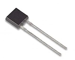
Varactor Diode
Substitutions of Varactor Diode
[Click Here for Sample Questions]
These are the substitutes of varactor diode:
- 1N400X series rectifier diodes
- Schottky rectifiers
- Various transistors used with their collector base junctions reversed biassed
- Makeshift varicaps include LEDs
Things to Remember
- Varactor diodes are the type of pn junction diodes whose internal capacitance can be changed by applying the reverse bias voltage.
- Capacitance is inversely proportional to the reverse voltage in the case of a varactor diode.
- Varicap, varactor, variable capacitance diode, variable reactance diode, tuning diode are the different names of the varactor diodes.
- Schottky rectifiers are the substitutes of varactor diodes.
- It is used as a voltage controlled capacitor.
- Commonly used in voltage controlled oscillators
Also Read:
Sample Questions
Ques: What is the varactor diode? (2 marks)
Ans: Varactor diodes are the type of pn junction diodes whose internal capacitance can be changed by applying the reverse bias voltage. These diodes are also known as the varicap diodes. Term varicap refers to the variable capacitance. The term varactor also refers to the variable reactance.
Ques: Draw the symbol of varactor diode. (2 marks)
Ans: Anode Cathode
Ques: What are the different names of varactor diodes? (2 marks)
Ans: Varicap, varactor, variable capacitance diode, variable reactance diode, tuning diode these are the different names of the varactor diodes.
Ques: What are the different substitutes for the varactor diode? (2 marks)
Ans: These are some substitutions of varactor diode:
- 1N400X series rectifier diodes
- Schottky rectifiers
- Various transistors used with their collector base junctions reversed biassed
- Makeshift varicaps include LEDs
Ques: State the applications of varactor diode. (3 marks)
Ans: These are some applications of varactor diode:
- FM radio and TV receivers
- Self adjusting bridge circuits
- Adjustable bandpass filters
- Very low noise microwave parametric amplifiers
- Tuning of LC resonant circuits in microwave frequency multipliers
- Voltage control oscillators
- Frequency and phase modulators
Ques: Why is a varactor diode used in RF communication systems? (3 marks)
Ans: Varactor term refers to the variable reactance. As we change the applied reverse bias voltage, its capacitance or in other words its reactance will change. And this property of the varactor diode is more useful in many applications.
Particularly when we want to change the capacitance in the circuit using the external applied voltage, then these varactor diodes are very useful. So, because of this property they are used in the RF communication systems.
Ques: Plot between reverse voltage and capacitance of varactor diode and explain it. (3 marks)
Ans: As we increase the reverse voltage the capacitance is going down, capacitance is going down here, at a low reverse voltage the capacitance is highest and increasing the voltage the capacitance decreases. So the capacitance is inversely proportional to the reverse voltage in case of a varactor diode.
Ques: What is the structure of a varactor diode? (3 marks)
Ans: The varactor diode is a pn junction diode, at the P side there is a hole and at the N side there are electrons. Positively charged at holes are the and negatively charged at electrons. So therefore force on holes in the direction of the electric field, the depletion region width is W, Both holes and electrons are pushed away from the depletion region (W), because the width of the depletion region increases.
When we apply reverse bias in the pn junction the depletion region (Dielectric) increases.
Ques: Why is the varactor diode called the variable capacitor diode? OR What is the working principle of a varactor diode? (5 marks)
Ans: The width of the depletion region increases as the reverse bias voltage across the pn junction also increases.
Here is the case of varactor diode-
P and N region are analogous to conducting plates of the capacitor
As we increase the reverse voltage the depletion region (Dielectric) width also increases
C α1/ W
Here capacitance is inversely proportional to the width of the depletion region and the capacitance decreases.
W is the width of depletion region
We can say that,
CT α1/ W
CT – Junction capacitance or transition capacitance is inversely proportional to the width of the depletion region (Dielectric W)
Transition capacitance varies inversely with the reverse voltage.
By varying the reverse voltage it is easy to control the capacitance of the junction, so that varactor diode is the variable capacitor diode.
For Latest Updates on Upcoming Board Exams, Click Here: https://t.me/class_10_12_board_updates
Check-Out:



Comments