



Education Journalist | Study Abroad Lead
Zener Diode as a Voltage Regulator helps to regulate voltage across small loads. A Zener diode is a semiconductor device with a p-n junction causing the current to flow in a forward or backward direction. The current conducted by the diode in the reverse mode is constant and the voltage drop is also constant. Hence Zener diode as a voltage regulator is extremely useful in circuits. There is a typical flow of current from anode to cathode in a Zener diode.
- When loaded in the forward direction, Zener diode acts as a general-purpose diode with a silicon p-n junction.
- However, if the voltage exceeds a certain limit – the Zener or the breakdown voltage, the forward current can be reverted.
- Zener Diode acts as a voltage regulator when it is given reverse bias feedback.
- A small leakage current is generated until a constant voltage is obtained.
Key Terms: Voltage, Diode, Zener Diode, Semiconductors, Transistors, Current, Voltage Regulator
What is a Voltage Regulator?
[Click Here for Previous Year Questions]
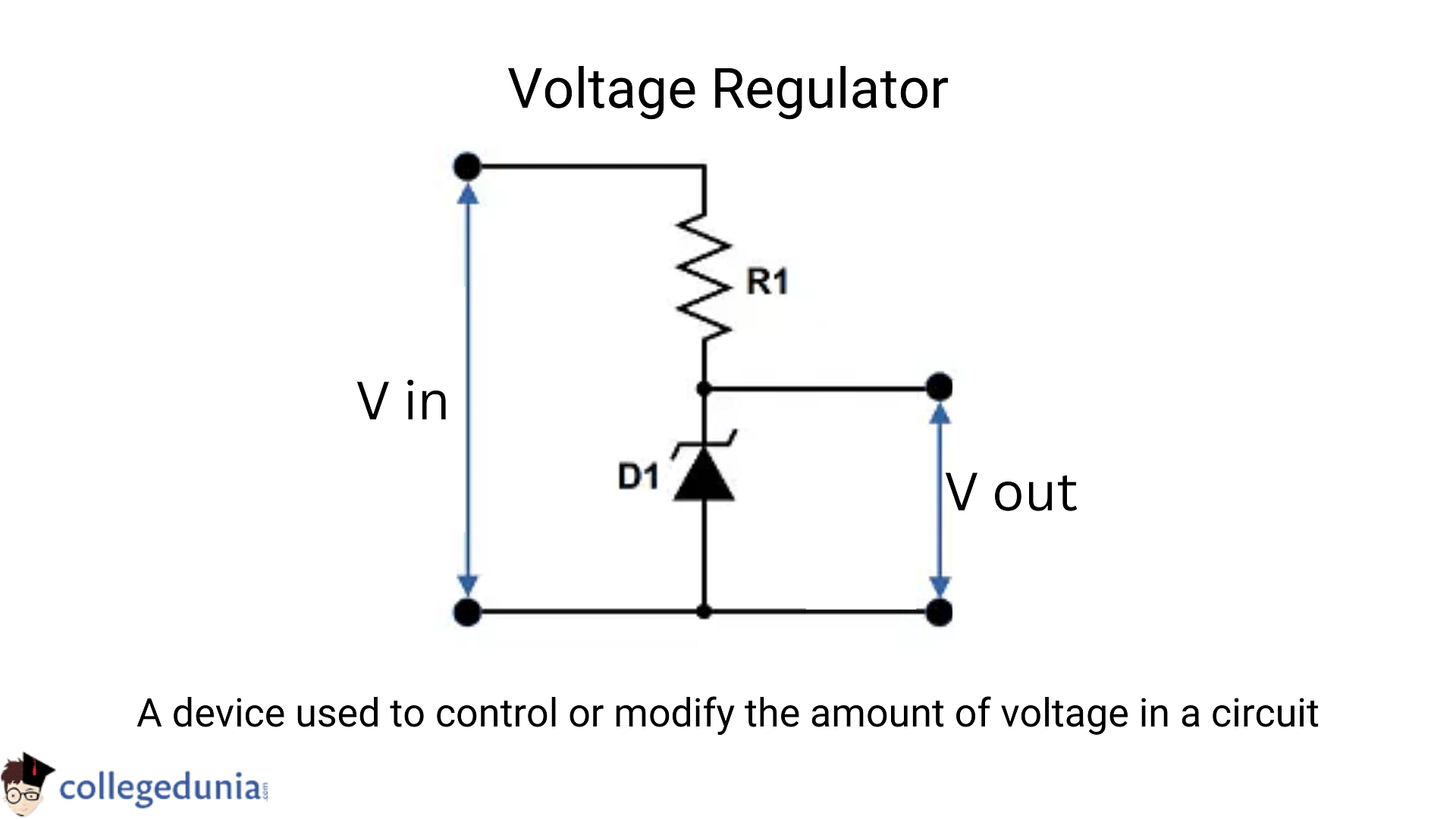
A voltage regulator is a device that controls the amount of voltage. It effectively steps down the input voltage to the correct level and maintains it throughout the supply. Hence, the voltage does not fall even when we apply a load. Voltage regulators are being used to control the output of the unit in computers, electric generators, and battery chargers. The voltage regulator is used for two main reasons:
- To control or modify the output voltage.
- To keep the level of voltage constant irrespective of the fluctuations in supply voltage.
The video below explains this:
Zener Diode as a Voltage Regulator Detailed Video Explanation:
Read More:
Zener Diode as a Voltage Regulator
[Click Here for Sample Questions]
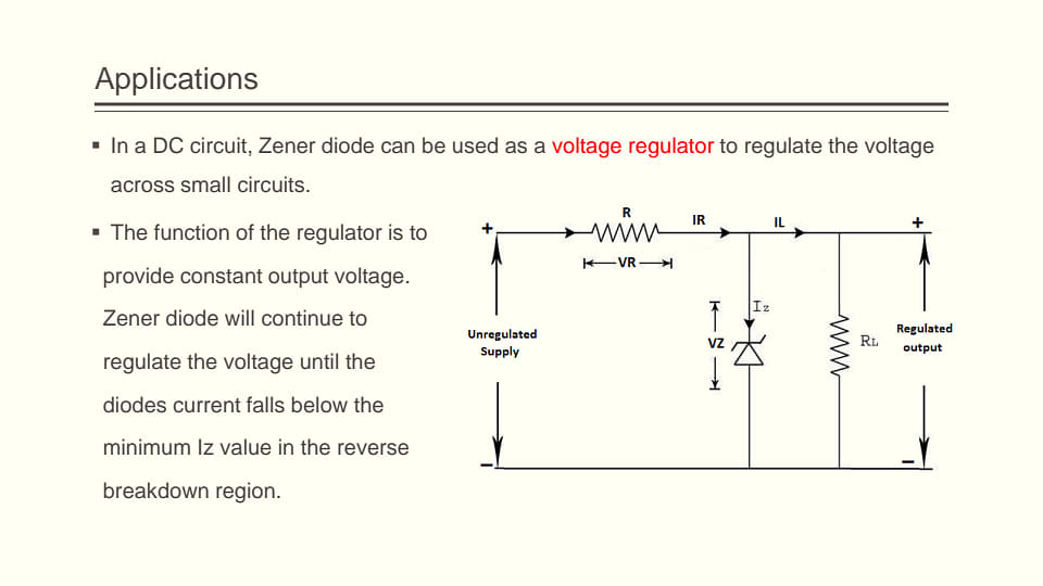
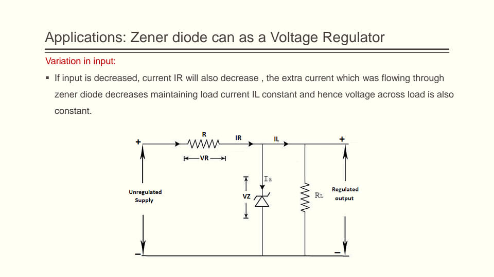
Zener diode acts as a voltage regulator in the following way –
- To limit the current flowing in a diode, a series resistor is connected to the circuit.
- The resistor is connected to the positive terminal of the DC.
- The resistor works in a way that the reverse-biased can also work in the breakdown conditions.
- An ordinary junction diode is not used as a low power rating diode can easily get damaged when a reverse bias is applied above the breakdown voltage.
- The Zener diode current should always be minimum when the maximum load current and the minimum input voltage are applied.
- To limit the current into the diode, a parallel resistor is attached to the circuit. It is connected to the Direct current.
- It is designed in a way that it can work in breaking situations as well.
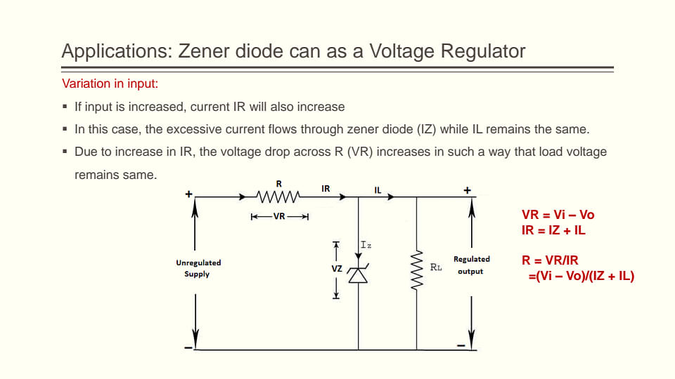
The value of the series resistor is RS = (VL − VZ)IL. The current through the diode increases when the voltage across the diode increases resulting in a voltage drop across the resistor. In the same way, the current through the diode decreases when the voltage across it tends to decrease. Therefore, the voltage drop across the resistor is less, and the output voltage results normally.
What is a Zener Diode?A Zener Diodes is used for voltage regulation, as surge suppressors, reference elements, and in switching applications and clipper circuits.
|
Shunt Voltage Regulators
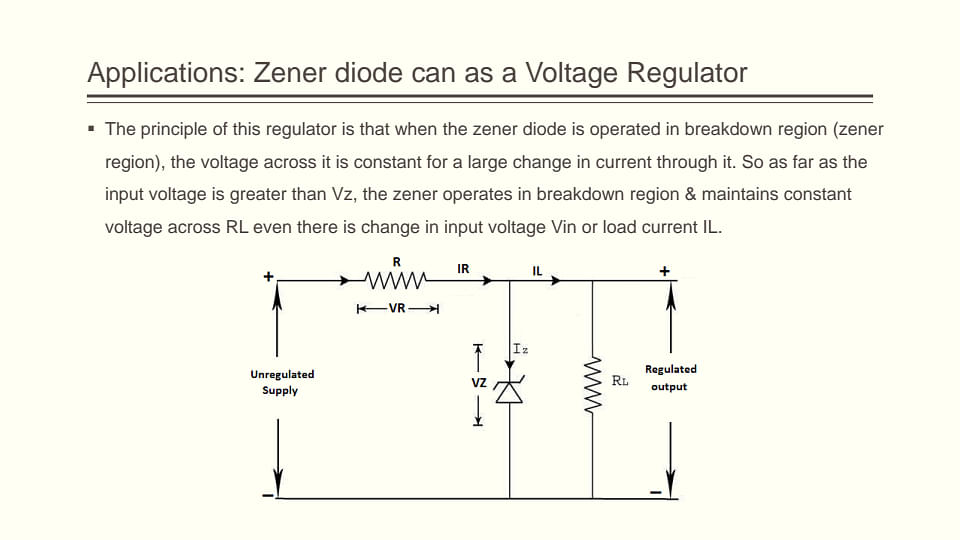
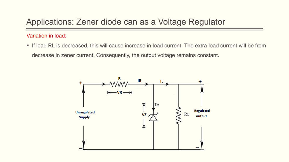
Zener Diodes are used as Shunt Voltage Regulators in order to regulate the voltage across small loads.
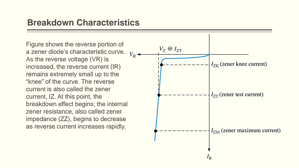
- Zener Diodes have sharp reverse breakdown voltage that will remain constant for a wide range of currents.
- Therefore, we connect the Zener diode parallel to the load so that the applied voltage will reverse bias it.
- Therefore, if the reverse bias voltage across the Zener diode exceeds the knee voltage, the voltage across the load will remain constant.
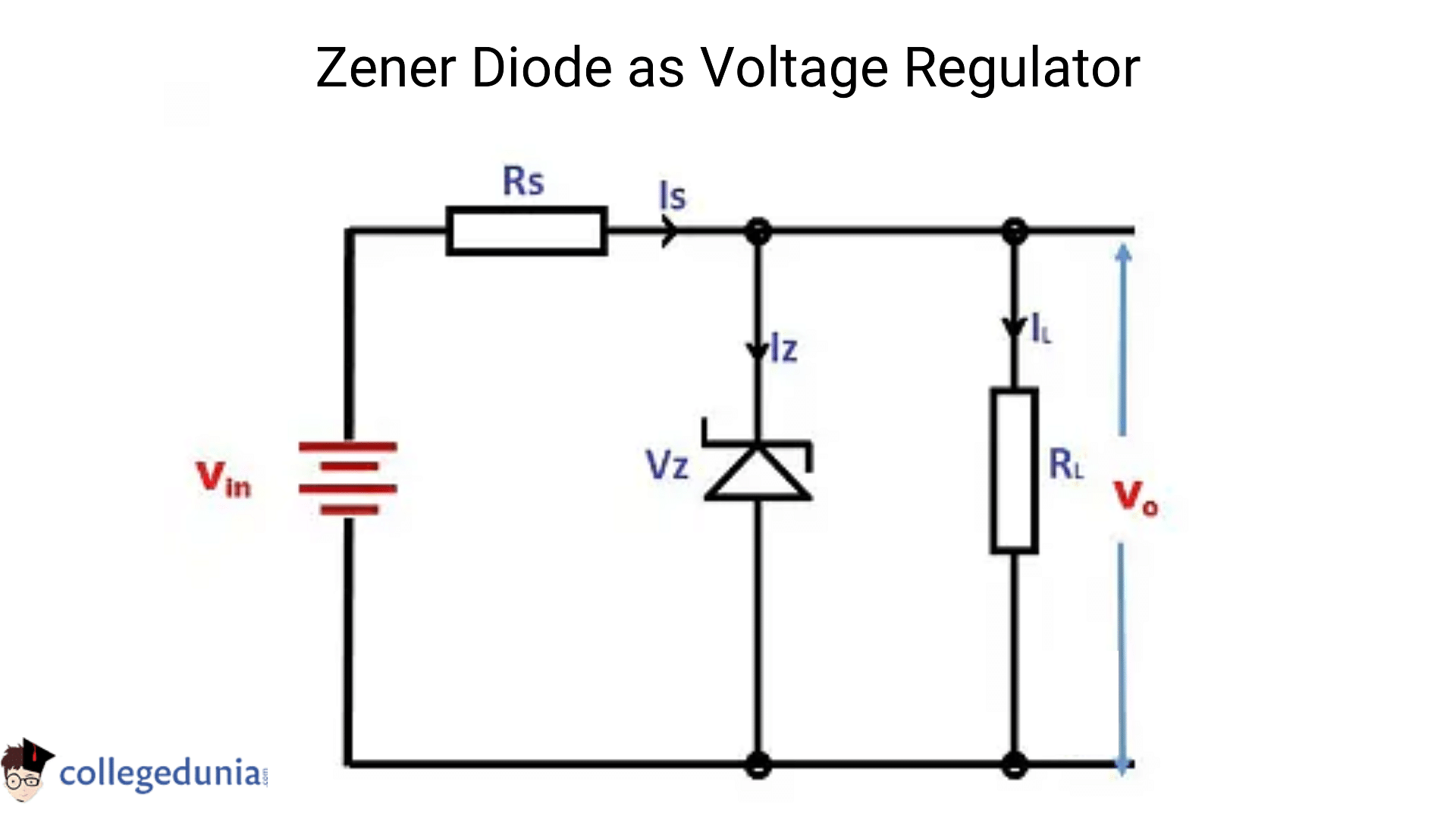
Zener diode as voltage regulator
Zener Diode as Voltage Regulator Formula
[Click Here for Previous Year Questions]
The maximum current that can flow through a Zener diode can be calculated using the formula,
IZM = \({P_{ZM} \over V_Z}\)
Where,
- IzM → Maximum Current that can flow through the Zener diode
- PzM → Maximum power the Zener diode can handle
- Vz → Zener voltage
Solved ExampleThe maximum current that a 15 Volt, 60 Watt Zener diode, can endure is – Iz = Pz / Vz = 60/15 = 4 A |
Applications of Zener Diode
[Click Here for Sample Questions]
The applications of Zener Diode are as follows –
- Zener diodes allow electricity to flow in a forward direction.
- When the voltage is over a specific level, Zener diodes also allow the current to flow in the opposite direction.
- The Zener voltage is the term given to the breakdown voltage.
- The Zener voltage in a conventional diode is high.
- If a reverse current greater than that value is allowed to travel through it, the diode will be completely wrecked.
- There is no reverse current flow in the reverse bias direction until the breakdown voltage is achieved.
- There is a significant rise in reverse current when this happens.
- The diode can withstand varying amounts of reverse current without being damaged.
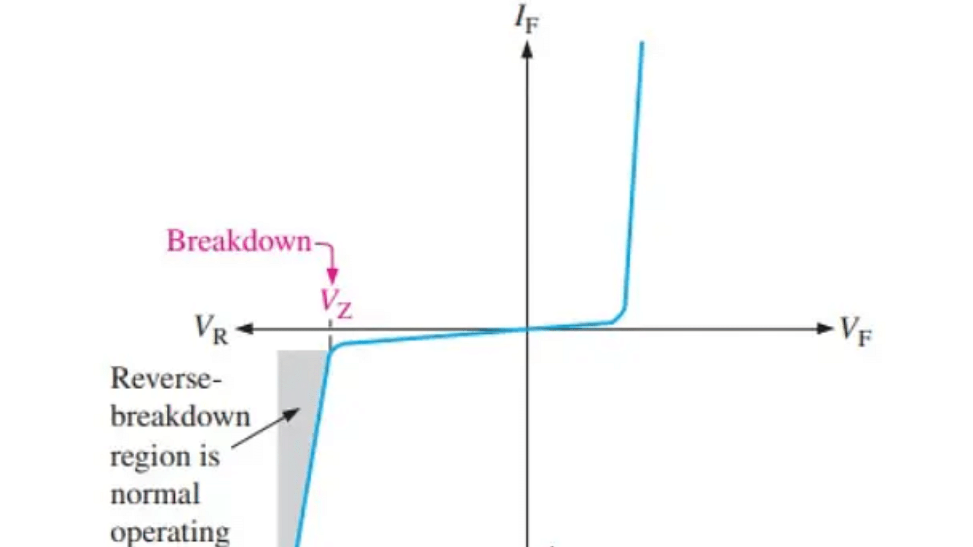
The breakdown voltage of Zener Diode
Advantages of Zener Diode
[Click Here for Previous Year Questions]
The advantages of Zener diode are –
- The Zener diode is less expensive than other diodes.
- A Zener diode can be used to regulate and stabilize the voltage in a circuit.
- Zener diodes have a high-performance standard.
- They can control the flowing current.
Working of Zener Diode
[Click Here for Sample Questions]
Zener diode is doped with impurities in the semiconductor material to enhance its conductivity.
- This thins out the depletion area.
- The application of electric fields in the depleted region is intensified even when a small voltage is applied to the system.
Important QuestionsQues. What happens when there is no biasing in the Zener Diode? When there is no bias in the Zener diode, the p-type semiconductor material has a valence band where electrons collide.
Ques. What happens when a reverse bias is applied in the Zener Diode? When a reverse bias is applied across the Zener diode, the diode conducts itself in a reverse-bias mode.
|
Zener Diode Regulator
[Click Here for Sample Questions]
Under fluctuating load current conditions, Zener Diodes can produce a stable voltage output with little ripple.
- A Zener diode will absorb enough current to produce a voltage drop of Output current if the current is passed through it from a voltage source through an appropriate current limiting resistor (RS).
- The DC output voltage from half- or full-wave rectifiers has ripple superimposed on it, and the average output voltage fluctuates when the load value changes.
- A steady output voltage can be obtained by adding a simple Zener stabilizer circuit across the output of the rectifier.
Frequently Asked QuestionsQues. Can Zener Diodes reduce DC Voltage? Ans. A Zener diode is designed in a way it can reduce a reverse voltage to a specified value. This makes Zener diodes efficient and low-cost voltage regulators. To use one in a circuit, the resistor value can be calculated, followed by connecting the resistor and Zener across the voltage that needs to be regulated. Ques. What are the disadvantages of the Zener diode voltage regulator? Ans. Disadvantages of Zener Diode Voltage Regulator are:
|
Zener Diode as a Voltage Regulator PDF Notes
[Click Here for Previous Year Questions]


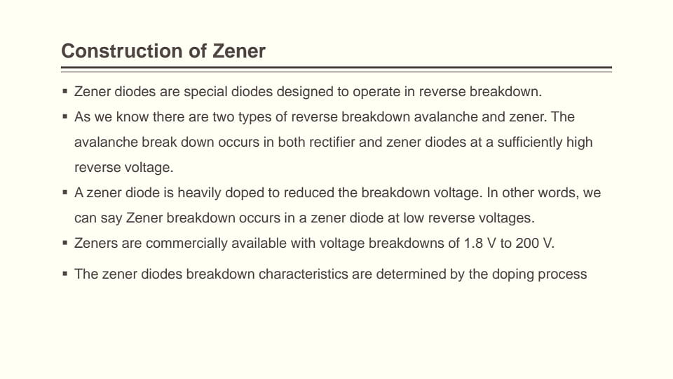








Zener Diode PDF
Things to Remember
- Zener Diode as a voltage regulator is use of a reverse bias in order to ensure that the voltage remains stable.
- A voltage regulator is a device that controls the amount of voltage.
- There is no reverse current flow in the reverse bias direction until the breakdown voltage is achieved.
- The Zener diode current should always be minimal when the minimum voltage level and maximum load current are used.
- The maximum current that can flow through a Zener diode can be calculated using the formula Pz = Vz x Iz
Read More:
Previous Year Questions
|
Sample Questions
Ques. Why is Zener Diode Used as a Voltage Regulator? (2 marks)
Ans. The Zener diode was developed particularly for this reason. The semi-conductive silicone material used in the Zener diode as a voltage regulator experiment allows it to perform without breaking down in both forward and reverse voltages. This would not be possible with a normal diode.
Ques. How does Zener Diode Act as a Voltage Regulator? (2 marks)
Ans. There is a little leakage current when the Zener diode is given reverse bias input until it reaches the breakdown voltage or a dc output. The current begins to flow without interruption at this point, with no change in voltage. As a result, the constant voltage aids the Zener Diode's function as a voltage regulator.
Ques. Explain the VI characteristics of Zener Diode. (2 marks)
Ans. When a diode is in forwarding bias mode, the Zener diode is just an ordinary diode. However, when the reverse bias is applied, the reverse voltage rises. This leads to complete breakdown in the Zener diode.
This breakdown helps the current to flow in a reverse direction, which is called a breakdown voltage. The resistance present in Zener Diode makes the breakdown linear or vertical. Thus, the Zener diode’s voltage is given by the following equation -V = VZ + IZRZ.
Ques. What is a Zener breakdown? (2 marks)
Ans. Zener reduction takes place when a Rectifier and a Zener diode collapse at the same time.
Ques. On which factor does the reverse breakdown voltage depend? (2 marks)
Ans. It depends upon the level of doping of the re-type and p-type sections of the diode. General-purpose diodes have each section lightly doped. They have a high value of reverse breakdown voltage. Zener diodes have each section heavily doped. They have a low value of reverse breakdown voltage.
Ques. What is the Knee voltage? (2 marks)
Ans. The forward voltage beyond which the current starts to increase rapidly with voltage is called the cut-in or Knee voltage of the diode.
Ques. Name the semiconductor device that can be used to regulate an unregulated DC power supply. With the help of the 7-V characteristics of this device, explain its working principle. (Delhi 2011) (2 marks)
Ans. Zener diodes are used as voltage regulators.
Principle: Zener diode is operated in the reverse breakdown region. The voltage across it remains constant, equal to the breakdown voltage for a large charge in reverse current

Characteristics of a Zener diode
Ques. How is a Zener diode fabricated so as to make it a special-purpose semiconductor diode? Draw the circuit diagram of a Zener diode as a voltage regulator and explain its working. (CBSE 2009) (2 marks)
Ans. Zener diode fabrication Zener diode is made by heavily doping both p and n-type semiconductors and hence, the width of the depletion layer becomes thin which leads to producing a large electric field to increase the current even on applying a reverse voltage of 4 or 5 V.
(i)Zener diodes are used as a voltage regulators.
Principle Zener diode is operated in the reverse breakdown region. The voltage across it remains constant, equal to the breakdown voltage for a large charge in reverse current

Characteristics of a Zener diode
Ques. Write the main use of the (i) photodiode (ii) Zener diode (CBSE 2010) (2 marks)
Ans. The main use of photodiodes is in the demodulation of optical signals and detection of the optical signal. The main use of Zener diodes is as a DC voltage regulator.
Ques. Explain with the help of a circuit diagram how a Zener diode works as a DC voltage regulator. Draw its I-V characteristics. (CBSE 2009) (2 marks)
Ans. Zener diodes are used as a voltage regulators.
Principle: Zener diode is operated in the reverse breakdown region. The voltage across it remains constant, equal to the breakdown voltage for a large charge in reverse current


Ques. Identify the semiconductor diode used.
(ii) Draw the circuit diagram to obtain the given characteristic of this device.
(iii) Briefly explain how this diode can be used as a voltage regulator. (Delhi 2008) (2 marks)
Ans. (i) Zener diode
(ii) From the figure, it is clear that the device, X, is a full-wave rectifier. Circuit diagram as shown in the figure below:

Zener diode connected with unregulated DC voltage in reverse bias. When the input voltage increases, then-current through R, increases and hence, the voltage drop across Rp increases while the voltage across the Zener diode remains constant. The voltage across the Zener diode remains constant beyond Zener voltage and hence, the same/constant regulated voltage is obtained across RL.
(iii) Zener diode is used as a voltage regulator.
Principle: Zener diode is operated in the reverse breakdown region. The voltage across it remains constant, equal to the breakdown voltage for a large charge in reverse current

Ques. A Zener diode with a breakdown voltage of 15 V is used in a voltage regulator circuit as shown below. What will be the current through the diode? (3 marks)

Ans. The voltage across the Zener diode is constant
Hence, i) 1k\(\Omega \) = \({15V \over 1k \Omega} = 15mA\)
250\(\Omega \) = \({20-15V \over 250 \Omega} = 20 mA\)
Therefore, current through Zener diode = (20-15) = 5mA
Ques. What is the current through the Zener Diode for the given circuit? The Zener diode breakdown voltage is given as 5.6 V. (3 marks)

Ans. Given, Vz = 5.6 V
i2 = Vz/800 = 7mA
⧍V across 200 \(\Omega \) = 9 – 5.6 = 3.4 V
i1 = 3.4/200 =17mA
i1 = i2 + iz
iz = 17mA − 7mA
=10mA
Ques. What is an equivalent circuit of zener diode? (3 marks)
Ans. Zener diode is a semiconductor device allowing current to flow either in a forward or reverse direction. Since it is highly doped, it has a high voltage gradient and thin depletion layer.
- The equivalent circuit of an ideal zener diode is a DC battery or a constant voltage source.
- In the case of a practical Zener diode, however, it is represented through a small dynamic resistance put in series with a DC battery.
Ques. For the circuit given below, find: (5 marks)
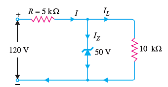
(i) the output voltage
(ii) the voltage drop across the series resistance
(iii) the current through Zener diode.
Ans. If we remove the Zener diode in the diagram, the voltage across the open circuit can be given by:
\(V = \frac{R_LE_i}{R + R_L} = \frac{10*120}{5+10} = 80V\)
Since the voltage across the Zener diode is greater than VZ which is 50 V, the Zener is in the “on” state. Therefore, it can be represented by a battery of 50 V.
- Therefore, the output voltage = VZ = 50V
- Voltage drop across the resistance = Input voltage – Vz = 120 – 50 = 70 V
- Load current = Vz/RL = 5 mA
Current through R, I = 70V/5 k Ohm = 14 mA
Applying Kirchhoff’s first law, I = IL + IZ
Therefore, the current through the Zener diode = I – IL = 14 – 5 = 9 mA
Ques. What is Zener Resistance? (2 marks)
Ans. Zener Resistance can be understood as the opposition offered to the flow of electricity passing through the Zener diode in the operating region.
Ques. What is the formula for calculating the Zener resistance? (2 marks)
Ans. The formula that gives Zener resistance is Zener Resistance = Zener voltage/Zener current
Rz = Vz/Iz
Ques. Is the Zener diode used as a surge suppressor? (1 mark)
Ans. Yes, the Zener diode is used to suppress transients as it clamps the currents that can be potentially damaging away from the protected load.
Ques. What are the limitations of the Zener diode voltage regulator? (2 marks)
Ans. A Zener diode has the following limitations –
- It has low efficiency for the heavy load current. As the load current is large, there will be significant power loss in the series limiting resistance.
- If the load changes, the output voltage also slightly changes.
Ques. The diode in the Zener diode shunt voltage regulator is regulated in what condition? (1 mark)
Ans. In a Zener diode shunt voltage regulator, the diode remains regulated as long as it is kept in the reverse condition.
For Latest Updates on Upcoming Board Exams, Click Here: https://t.me/class_10_12_board_updates
Check-Out:



Comments