



Content Curator
Resistor is a component of an electrical circuit offering certain opposition to the flow current in that circuit. Resistors are the most significant and widely used components in electrical circuits. It is a two-terminal passive electrical component that is used to regulate the flow of electricity in a circuit.
- A passive electrical component does not generate power, but it dissipates, stores, and/or releases it. Passive elements include resistances, capacitors, and coils.
- The main purpose of using a resistor in an electrical circuit is to reduce the current flow, divide voltage, and adjust signal levels, among other uses.
- A Fixed resistor does not vary its resistance value. Its resistance changes slightly with temperature, time, or operating voltage.
- A variable resistor is a resistor in which the electric resistance value can be adjusted.
| Table of Content |
Key Terms: Resistance, Electrical Circuit, Insulators, Conductors, Ohm’s Law, Ampere, Potential Difference, Voltage, Resistivity, Color coded resistors, Electric Current, Electricity
What is Resistor?
[Click Here for Sample Questions]
A resistor is a two-terminal passive electrical component that produces opposition in the flow of electric current. They can be found in almost electrical networks and electronic circuits.
- Resistors are electrical devices whose function is determined by their resistance.
- Resistance is the measure of the opposition to current flow in an electric circuit. It is defined as the ease with which electrons enable electricity to flow through them.
- Resistance is the electrical quantity utilized by the resistor to regulate the flow of electrons.
- An insulator has a higher resistance than a conductor.
- The SI unit of resistance is Ohm (Ω).
- The higher multiple and sub-multiple values of Ohm are known as kilo ohms (KΩ), mega ohms (MΩ), and so on.
- An Ohm is a resistance defined as a current flowing through a resistor whose terminals drop one volt when one ampere passes through them.
- The resistivity of a material is equal to the resistance of an object of that material of 1 m length and 1 m2 area of cross-section.
According to Ohm's law, the voltage V across a resistor is precisely proportional to the current I flowing through it.
As a result, V = IR
Where R is the resistance of the resistor.

Symbols of Resistor
Discover about the Chapter video:
Current Electricity Detailed Video Explanation:
Also Read:
| Topic Related Concepts | ||
|---|---|---|
| Voltage | Electrical Circuit | Current Electricity |
| Potential Difference | Power | Heat |
| Insulators | Conductors | Semiconductor devices |
Types of Resistor
[Click Here for Previous Year Questions]
Many different types of resistors are used in electronic circuits. These resistors are classified depending on their manufacture and construction. Resistors are divided into two broad types:
- Linear Resistors
- Non-linear Resistors linear resistors and non-linear resistors.
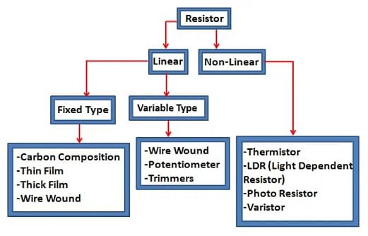
Different Types of Resistors
Linear Resistors
Linear resistors are resistors whose values change when applied voltage and temperature change. Linear resistors are further classified as:
- Fixed Resistors: A Fixed resistor does not vary its resistance value. Its resistance changes slightly with temperature, time, or operating voltage. Carbon composition resistors, Thin film resistors (Carbon film resistors and Metal film resistors), Thick film resistors (Fusible resistors, Cermet film resistors, and Metal oxide resistors), and Wire wound resistors are examples of fixed resistors.
- Variable Resistors: A variable resistor is a resistor in which the electric resistance value can be adjusted. PotentiometerTrimmer, Rheostat Resistor, and Trimmer Resistor are the types of Variable Resistors.
Non-Linear Resistors
In non-linear resistors, the electric current flowing through them changes according to the temperature or voltage applied but does not follow Ohm's law. The most commonly used non-linear resistors are Thermistors, Light Dependent resistors (LDR), Photo Resistors, and Voltage-Dependent Resistors (also known as varistors).
Color Coding of Resistors
[Click Here for Sample Questions]
The resistance value is indicated with several colored bands around the component body of the resistor. This technique of marking developed in the 1920s.
- The significant digit of the resistance value is determined by the first two bands.
- The third band is the multiplying factor
- And the fourth band gives the tolerance. Each color represents a different number and can be looked up in a resistor color code chart.
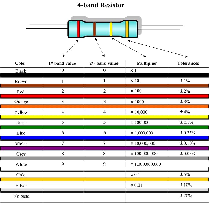
Example: Brown, Red, Red, Silver
Brown and Red represent 1 and 2, respectively. Those consist of the first and second digits, so it will be 12. The third band is Red. As a multiplier, it is × 100, therefore, it represents a 1200 ohm resistor. The fourth band, silver, represents the tolerance, so the final expression of the resistance is 1200 ± 10% Ω.
Read More: Current Electricity Important Questions
Working Principle of Resistor
[Click Here for Previous Year Questions]
The electrical energy is absorbed by the resistor in the process of acting as a barrier to the flow of electricity by lowering the voltage, and it is released as heat. Heat dissipation in today's modern circuits is generally a fraction of a Watt.
If I is the current flowing through the resistor in amperes and R is the resistance in ohms, then V is the voltage drop imposed by the resistor, according to Ohm's law:
V = IR
Another way to put it is that when the capacity difference between the ends of the resistor is 1 volt, the 1Ω resistor will allow a current of 1 amp.
In a DC circuit, if P is the power wasted by the resistor in watts:
V x I = P
We may represent power (watts) in terms of current and resistance by substituting in Ohm's law:
P = I2 / R
Power (watts) can also be expressed in terms of voltage and resistance:
P = V2 x R
Series and Parallel Circuits
[Click Here for Sample Questions]
An electrical circuit may have two or more resistors and they can be linked in both series and parallel configurations. A series connection occurs when two resistors are linked in a series path, and the current flowing through them is the same. The voltage across the resistors will be equal to the total voltage across each resistor.
If three resistors R1, R2, and R3 are in a series connection, the overall resistance R(total), will be:
R(total) = R1 + R2 + R3

Resistors in Series
A parallel connection is a series in which the resistors are linked in parallel. The voltage applied across each component remains constant in this case. The sum of the currents flowing through each resistor equals the total current flowing through the series.

Resistors in Parallel
If three resistors R1, R2, and R3 are linked in this circuit.
The total resistance R(total) will be
1/ R total = (1/ R1 + 1/ R2 + 1/ R3) i.e.,
Rtotal = (R1 x R2 x R3)/ (R1 + R2 + R3)
Power Dissipation
The power dissipation through a resistor is calculated using the equation below.
Power P = I2 x R = V x I = V2/R
Joule's first law was used to generate the first equation, while Ohm's law was used to derive the other two.
Do Check Out:
Previous Year Questions
- A wire has a resistance of 3.1… [TS EAMCET 2017]
- In a given circuit, all resistances are of… [VITEEE 2016]
- Which statement is correct for the given… [VITEEE 2016]
- A dc battery of V volt is connected to… [JEE Advanced 2010]
- Three resistors 1Ω, 2Ω and 3Ω are connected to form a triangle… [VITEEE 2012]
- Consider two identical galvanometers and two identical resistors with resistance… [JEE Advanced 2016]
- Column - I gives certain physical terms associated with flow of current through a metallic conductor… [NEET 2021]
- Ten identical cells connected in series are needed to heat a wire of length one meter and radius… [NEET 2013]
- The charge flowing through a resistance R… [NEET 2013]
- The effective resistance of a parallel connection that consists of four wires of equal length, equal area of cross-section… [NEET 2021]
Things to Remember
- A conductor is a material that allows electricity to flow through it, such as metal in addition.
- An insulator is a substance that prevents electricity from flowing through it, such as plastic or wood.
- Air, which is normally considered an insulator, may become a conductor when a large voltage builds up in the clouds, causing lightning.
- When the capacity difference between the ends of the resistor is 1 volt, the 1Ω resistor will allow a current of 1 amp.
- An insulator has a higher resistance than a conductor.
Sample Questions
Ques. What is the Resistor Classification? [3 marks]
Ans. Resistors are categorised as follows from the perspective of operation:
- Resistors that are fixed
- Carbon composition resistor — This is the most prevalent, with carbon clay as the resistive material and tin copper leads.
- Metalized resistor – This substance, similar to constantan, is composed of 60% copper and 40% nickel, and magnesium material has a high resistance.
- Wired wound type resistor — This type of resistor is created by depositing a thick film of resistive material into an insulating substance using a film deposition process.
- A variable resistor is employed in circuits where it has to be adjustable in order to stay linked to the circuit frame. In general, they have three leads that are two fixed and one movable.
Ques. What is Resistor Color Coding? [5 marks]
Ans. Although resistors do not show their value outside, the colour pattern created by their resistance may be determined. Color-coding is used on PTH (plated-through-hole) resistors (which adds a lot of flare to circuits), and SMD (surface-mount-device) resistors have their own value-marking scheme.
The table below shows the colour codes for resistors:
| Color | Color Code |
|---|---|
| Black | 0 |
| Brown | 1 |
| Red | 2 |
| Orange | 3 |
| Yellow | 4 |
| Green | 5 |
| Blue | 6 |
| Violet | 7 |
| Grey | 8 |
| White | 9 |
Ques. What are the applications of Resistors? [3 marks]
Ans. Resistors are used in the following ways:
- Wire-wrapped resistors are used in shunt with ampere meter applications where balanced current management, high sensitivity, and precise measurement are required.
- Photo resistors are used in flame detectors, burglar alarms, and photographic equipment, among other things.
- Temperature and voltmeter control is achieved by the use of resistors.
- Digital multimeters, amplifiers, telecommunications, and oscillators all require resistors.
- Modulators, demodulators, and transmitters all employ them.
Ques. State Ohm’s law. [2 marks]
Ans. According to Ohm’s Law, the electric current flowing through a conducting wire, I, is directly proportional to the potential difference across its ends, V, provided its temperature stays unchanged.
Therefore, V∝I.
Ques. What is electric current? Define. [1 mark]
Ans. Electric Current is the amount of charge ‘Q’ flowing through a particular area of cross section in unit time ‘t’, i.e.
Electric current, I = Q/t
Ques. When is the potential difference is equal to 1 volt in an electric circuit? [2 marks]
Ans. Potential difference between two points of a circuit is said to be 1 volt when a work of 1J is to be done for moving a charge of 1 C between these two points.
Ques. Is resistivity directly proportional to temperature? [2 marks]
Ans. No, Resistivity is indirectly proportional to the temperature. In other words, if the temperature of the material increases, its resistivities will decrease.
Ques. Three resistors of 10Ω, 10Ω, and 15Ω are connected in parallel. Find their equivalent resistance. [3 marks]
Ans. The given resistors are R1 = 10Ω, R2 = 10Ω, R3 = 15Ω and R1, R2 and R3 are connected in parallel, then the equivalent resistance (R) is given by the formula,
1/R = 1/R1 + 1/R2 + 1/R3
= 1/10 + 1/10 + 1/15
= 16/60
Hence equivalent resistance, R = 60/16 = 4.25 Ω.
Ques. What causes resistance? [2 marks]
Ans. An electric current flows when electrons travel through a conductor, for example, a metal wire. Moving electrons can collide with ions in the metal. This makes it more difficult for the current to flow and thus causes resistance.
Ques. A given length of a wire is doubled on itself and this process is repeated once again. By what factor does the resistance of the wire change? [2 marks]
Ans. Length becomes one-fourth of the original length and the area of the cross-section becomes four times that of the original.
i.e. I2 = \(\frac{1}{4}\)I1 and A2 = 4A1
∴ \(\frac{R_2}{R_1} = \frac{I_2}{I_1}\) x \(\frac{A_1}{A_2}\) = \(\frac{1}{4}\) x \(\frac{1}{4}\) = \(\frac{1}{16}\)
⇒ R2 = \(\frac{1}{16}\)R1
So, the new resistance is (1/16)th of the original resistance.
For Latest Updates on Upcoming Board Exams, Click Here: https://t.me/class_10_12_board_updates
Check Out:



Comments