



Content Curator
Circuit Diagram is a visual representation of an electrical circuit using either industry standard symbols or basic images of parts. A circuit diagram, also known as an electrical diagram, elementary diagram, or electronic schematic, is used for the design, construction, and maintenance of electrical and electronic equipment. The components of a circuit diagram are Electric Cell, Battery, Wire joint, Wires crossing without joining, Electric bulb, and Resistor.
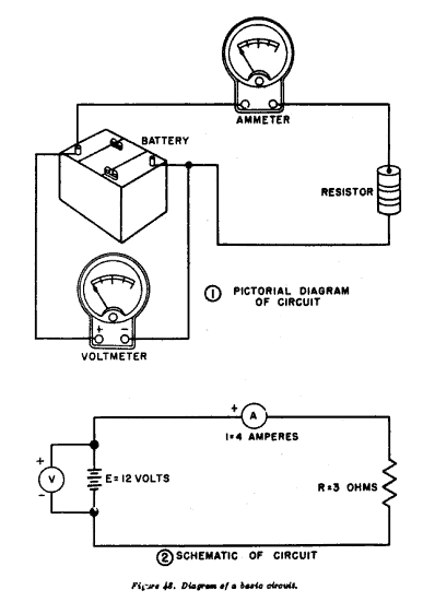
Circuit Diagrams
Also read: Current Electricity Ncert Solutions
Very Short Answer Question [1 Mark Questions]
Ques. When a potential difference is applied across the ends of a conductor how does the random motion of free electrons in a conductor get affected? (Comptt. Delhi 2014)
Ans. Random motion of free electrons gets directed towards the point at a higher potential when a potential difference is applied across the ends of a conductor.
Ques. How can one explain the increase in resistivity of metal with an increase in temperature? (Comptt. All India 2014)
Ans. With the increase in temperature, the relaxation time (average time between successive collisions) decreases, and hence resistivity increases. Also,
ρ = m/me2r
resistivity increases, as x, decreases with an increase in temperature.
Ques. Two students A and B were asked to pick a resistor of 15 kΩ from a collection of carbon resistors. A picked a resistor with bands of colors: brown, green, and orange whereas B chose a resistor with bands of black, green, and red. Who picked the correct resistor? (Comptt. All India 2013)
Ans. Student ‘A’ picked up the correct resistor of 15 kΩ.
Ques. Define the Internal resistance of a cell.
Ans. The internal resistance of a cell is defined as the opposition offered by the electrolytes and electrodes of a cell to the flow of current through it. It mainly depends on the electrolytes and electrodes of a cell.
Ques. What is an electric cell?
Ans. The electric cell can be defined as the energy source that converts chemical energy into electrical energy. It consists of two terminals, where one terminal is positive, and another terminal is negative.
Ques. _____ is the region on an electrical circuit between two circuit elements, the region is represented as a dot or a small filled circle.
- Wire
- Resistor
- Node
- Electrical element
Ans. c) Node
Ques. What is used to increase the output signal in the electrical circuit?
- Capacitors
- Amplifier
- Resistor
- Inductors
Ans. The correct answer is b) Amplifier
Also read: Combination of Resistors
Short Answer Question [2 Marks Questions]
Ques. A graph showing the variation of current versus voltage for a material GaAs is shown in the figure. Identify the region of
(i) negative resistance
(ii) where Ohm’s law is obeyed versus for a GaAs is in the Identify the region of. (Delhi 2014)
Ans. DE: Negative resistance region.
AB: Where Ohm’s law is obeyed.
Ques. To produce 103 joules of heat in 10 seconds, how much voltage should be applied to 100-ohm resistance?
Ans. Given
- Heat, H = 103 J
- time, t = 10 s
- Resistance, R = 100 ohm
We know, Heat energy H, is given by
H = V2t/R
⇒ V2 = HR/t
\(\Rightarrow V=\sqrt{\frac {HR}{t}}\)
\(\Rightarrow V=\sqrt{\frac {10^3 \times 100}{10}}\)
⇒ V = 100 volt
Ques. Using the mathematical expression for the conductivity of a material, explain how it varies with temperature for
(i) semiconductors,
and (ii) good conductors. (All India 2008)
Ans. Conductivity σ = ne2τ/m
(i) Semiconductors: The conductivity of semiconductors increases with the increase in temperature. It is due to an increase in V. It dominates the effect caused by a decrease in ‘x’.
(ii) Good conductors: With the increase in temperature, the conductivity of good conductors decreases. It is due to a decrease in the value of relaxation time. The effect of the increased value of V is negligible.
Read more: Limitations of Ohm’s Law
Ques. A cell of emf ‘E’ and internal resistance V is connected across a variable resistor ‘R’. Plot a graph that shows the variation of terminal potential ‘V’ with resistance R.
Predict from the graph the condition under which ‘V’ becomes equal to ‘E’. (Delhi 2009)
Ans. (i) V = ε – Ir gives the terminal voltage and can be plotted as shown in Figure 1.
(ii) The graph between V and R, is shown in Figure 2.

V becomes E when no current is down.
Ques. Nichrome and copper wires of the same length and same radius are connected in series. Current I is passed through them. Which wire gets heated up more? Justify your answer. (Outside Delhi 2017)
Ans. Nichrome :
Nichrome wire gets heated up more because of the higher resistivity of nichrome.
ResistivityNI > ResistivityCu
Long Answer Questions [3 Marks Questions]
Ques. A battery of emf 10 V and internal resistance 3Ω is connected to a resistor. If the current in the circuit is 0.5 A, find
(i) the resistance of the resistor;
(ii) the terminal voltage of the battery. (Comptt. Delhi 2012)
Ans. (i) As I = V/r + R
therefore, 10/ r + R = 0.5
or, 10/3 + R = 0.5
or, 100/5 = 3 + R
therefore, R = 20 – 3 = 17Ω
(ii) As V = IR
therefore, V = 5/10 x 17 = 85/10 = 8.5V.
Ques. The network PQRS, shown in the circuit diagram, has batteries of 4 V and 5 V and negligible internal resistance. A milliammeter of 20 Ω resistance is connected between P and R. Calculate the reading in the milliammeter. (Comptt. All India 2012)

Ans. By applying the loop rule to loop PQRP
-4 = 60(I – I1) – 20 I1 = 0
or, – 4 = 60I – 60I1 – 20I1
Dividing the above equation by 4, we get
or, 20I1 -15 I = 1 …(i)
By applying the loop rule to loop PRSP, we get
-5 + 200 I + 20 I1 = 0
Dividing the above equation by 5, we get
4I1 + 40 I = 1 …(ii)

∴ Reading of milliammeter = 0.064 A
Ques. A cell of emf E and internal resistance r is connected to two external resistances R1 and R2 and a perfect ammeter. And the current in the circuit is measured in four different situations:
(i) without any external resistance in the circuit
(ii) with resistance R2 only
(iii) with R1 and R2 in series combination
(iv) with R1 and R2 in parallel combination
The currents measured in the four cases are 0.42A, 1.05A, 1.4A, and 4.2A, but not necessarily in that order. Identify the currents corresponding to the four cases mentioned above.
Ans.

Read more:
Very Long Answer Questions [5 Marks Questions]
Ques. Write the principle of a potentiometer. With the help of a circuit diagram describe briefly, how this device is used to compare the emf’s of two cells. (Comptt. All India 2012)
Ans. A potentiometer is a device used to measure potential differences.

Principle of a potentiometer: The basic principle of a potentiometer is that the potential drops across any length of the wire are directly proportional to that length when a constant current flows through a wire of uniform cross-sectional area and composition.
V ∝ l, V = Kl [where K is the potential gradient]
Close the key K1. A constant current flows through the potentiometer wire. With key K2 kept open, move the jockey along AB till it balances the emf e of the cell.
Let us assume l as the balancing length of the wire. If K is the potential gradient, then the emf of the cell will be

ε = Kl1 ….. (i)
With the help of resistance box R.B, a resistance R has been introduced and close key K2. Find the balance point for the terminal potential difference V of the cell. If l2 is the balancing length, then;
V = Kl2 ….. (ii)
Dividing (ii) by (i), we have ε/V = Kl1/Kl2 = l1/l2
Let r be the internal resistance of the cell ε = I (R + r) and V = IR

Ques. With the help of a circuit diagram describe briefly, how a potentiometer is used to determine the internal resistance of a cell. (All India 2013)
Ans. The apparatus is set up as per the circuit diagram shown below.

The cell (emf ε) is connected across a resistance box through a key K2, as shown in the figure. With key K2 is open, balance is obtained at length l1 (AN1), then,
e = Φl1 ….. (i)
When key K2 is closed, the cell sends a current (I) through the resistance box (R). If V is the terminal potential difference of the cell and balance is obtained at length l2 (AN2)
V = Φl2 ….. (ii)
So, we have e/V = l1/l2 ….. (iii)
But, e = I(r + R) and V = IR, which gives
e/V = (r + R/R) ….. (iv)
From (iii) and (iv), we get,
R + R/R = l1/l2
= r = R ( l1/l2 – 1) …. (v)
Using equation (v) we can find the internal resistance of the cell.
Check Out:



Comments