



Education Journalist | Study Abroad Lead
Circuit Diagram is a graphical representation of an electric circuit. It is useful for determining the usage of an electric circuit in terms of designing, constructing, and maintaining of electrical and electronic devices. Circuit diagram can also be known as an elementary diagram or electronic schematic diagram. It majorly defines the simplified graphical representation of an electric circuit.
Read Also: Resistivity Temperature Dependence
| Table of Content |
Key Terms: Circuit, Resistor, Electric Bulb, Battery, Electric Circuit, Electricity, Ammeter, Voltmeter, Electric Current, Elementary diagram, Electronic schematic diagram
What is a Circuit Diagram?
[Click Here for Previous Year Questions]
A circuit can be defined as a pavement that, in turn, is utilized by the electric current to travel. Therefore, a circuit diagram can be considered as a graphical demonstration of an electrical circuit.
- The electrical circuits are represented through the lines that denote the wires.
- Various other symbols are used to denote electronic & electrical constituents.
- It helps electricians in their field jobs as they are dependent upon an electric circuit diagram for initiating any wiring-related work.
A circuit diagram basically helps give a graphical representation of an electrical circuit. Circuit diagrams generally exhibit the relative positions of all the elements and their connections to each other.
Discover about the Chapter video:
Current Electricity Detailed Video Explanation:
Also Read:
Circuit Diagram Explanation
[Click Here for Sample Questions]
The graphical representation of an electrical circuit, a circuit diagram is also called an electrical diagram, elementary diagram or electronic schematic. Circuit diagrams are used for the design, construction and maintenance of electrical and electronic equipment.
A simple circuit diagram contains three components that are considered vital for operating an electrical circuit:
- Voltage source
- Conductive pathway (pathway facilitating the motion of charges)
- Resistor (Any bulb or motor requiring electricity for work)
Frequently Asked Questions Related to CircuitsQues. List some of the primary requirements of an electric circuit. (2 marks) Ans. Some of the primary requirements of an electric circuit are:
Ques. Name the device that is used to increase the output signal in the electrical circuit.
Ans: d) Amplifier Explanation: An amplifier can be expressed as a component that is used to increase the output signal. |
Circuit Diagram Examples
[Click Here for Previous Year Questions]
In the following circuit diagram, three 5 V batteries are used to power a circuit containing three light bulbs.
The above circuit diagram depicts that the light bulbs are connected to each other in series. But it is not always necessary to connect them in series and the three cells connected by wires. But it should be noted that it doesn’t necessarily need to be connected in series.
Components of a Circuit Diagram
[Click Here for Sample Questions]
A circuit diagram is a representation of an electrical circuit, therefore, its components are similar to that of an actual circuit. These components help in understanding and analyzing the circuit diagram in a better way. This analysis could be easily done with the help of the diagrammatic and symbolic representation of the components of a circuit diagram.
Electric Cell
The very first and the most essential component is an electric cell. It works as a source of current. And in its symbolic representation, the larger terminal is said to be positive whereas the smaller one is the negative terminal.

Electric Cell
Battery
Another essential component of an electrical circuit diagram is a battery which is a combination of cells. Its functions are defined similar to that of a cell and its diagrammatic representation could also be studied similar to that of a single cell.

Battery
Wire Joint
In a few circuit diagrams or in an electrical circuit, one device has to be connected to the other device and this is done using the wires. This is represented by drawing blobs at their point of connectivity.

Wire joint
Wires crossing without joining
In the circuit diagram, when the wires do not touch each other, they are drawn without blobs.

Wires crossing without joining
Electric bulb
This is an electrical device that uses electricity to glow and also works as a final check tool of an entire circuit diagram.

Electric Bulb
Resistor (R)
Resistor is simply used to restrict the amount of current flow in the entire electrical circuit.

Resistor
Ammeter
An ammeter is often utilised for measuring the current passing at a particular point.

Ammeter Symbol
Voltmeter
A voltmeter is often utilised for measuring the voltage between two points in a circuit.

Voltmeter symbol
Variable Resistance
Variable resistance, which is also often called rheostat, is majorly used to regulate the amount of current flow by increasing or decreasing the resistance to current flow.

Variable Resistance Symbol
Read Also:
Types of Electric Circuit Diagrams
[Click Here for Previous Year Questions]
The different types of electric circuit diagrams are as follows –
Block Diagram
- A Block diagram is considered one of the easiest approaches in order to display the complex electrical circuit in its simplest and most understandable form.
- In this approach, the complex interconnections or wiring are not actually considered so far, rather it displays the functioning of the principal components of an electric circuit.
- It depicts them in the form of blocks which is its main feature.
- The interconnecting lines tend to showcase the relationship between these blocks.
Schematic Circuit Diagram
- The schematic diagram is another approach to illustrate an electric circuit.
- It displays all the electrical components & interconnections of an electrical circuit by employing systemized symbols and lines.
- These diagrams are employed in the form of series and parallel combinations and the accurate linking between their terminals.
- For instance, while drawing a schematic diagram of a voltage amplifier, symbols must be employed for displaying the electrical components and lines to present the interlinking between their terminals.
Pictorial Circuit Diagram
- The pictorial circuit diagram is one of the fundamental and very important forms of diagrams that use only a set of simple images of electrical components.
- These diagrams usually present a sketch of any particular electrical components that are used in an actual circuit and the same goes with the interconnections between these.
- These circuit diagrams are easy to understand due to their simpler physical appearance.
For what purpose is a circuit diagram used?Circuit diagrams are generally utilised for the design, construction and maintenance of electrical and electronic tools and equipment. What are the type of symbols used in a circuit diagram?Electrical symbols of different electrical devices such as batteries, resistors and electric bulbs are often used in a circuit diagram. |
Things to Remember
- Circuit Diagram is a representation of an electric circuit. It is a graphical demonstration of an electrical circuit.
- The electrical circuits are represented through the lines that denote the wires.
- A circuit diagram is composed of various elements such as an electric cell, battery, wire joint, electric bulb, and resistor.
- A Block diagram is considered one of the easiest approaches in order to display a complex electrical circuit in its simplest and most basic form.
- The schematic diagram displays all the electrical components & interconnections of an electrical circuit by employing systemized symbols and lines.
- The pictorial circuit diagram is one of the fundamental and very important forms of diagrams that use only a set of simple images of electrical components.
Also Read:
Sample Questions
Ques. What is the use of a voltmeter? (1 marks)
Ans. The voltmeter is generally used for measuring the electric potential.
Ques. What is the use of an Ammeter? (1 marks)
Ans. The ammeter is used to measure the electric current
Ques. What is the main purpose of a circuit diagram? (2 marks)
Ans. Circuit diagrams are generally used for designing, construction, and also the maintenance of electrical and electronic equipment. And in academics, it helps students in easily understanding the phenomenon behind the electrical circuits.
Ques. What symbols are used in a circuit diagram? Why? (2 marks)
Ans. The circuit diagram uses multiple symbols of various electrical devices and components such as batteries, resistors, and electric bulbs, etc. Their symbols are used in a circuit diagram to represent them and complete the circuit diagram.
Ques. What is a simple circuit diagram? (2 marks)
Ans. A simple circuit diagram is a type of circuit diagram which contains the three basic components that are needed for an electric circuit to function. And the three basic components here are a source of voltage, a conductive path, and a resistor.
Ques. How pictorial diagram can be differentiated from a schematic diagram? (1 mark)
Ans. A pictorial circuit diagram uses simple images of components, while on the other hand a schematic diagram shows the components of the circuit as simplified standard symbols.
Ques. What is electric current? (1/5, Board Term 1,2017)
Ans. Electric current can be defined the amount of charge flowing through a particular area in unit time.
Ques. A current of 10 A flows through a conductor for two minutes. (i) Find out the amount of charge passed through any area of cross section of the conductor; (ii) If the charge of an electron is 1.6 × 10⁻¹⁹ C, then what will be the total number of electrons flowing? (Board Term I, 2013)
Ans. Given that: I = 10 A, t = 2 min = 2 × 60 s = 120 s
(i) Amount of charge Q passed through any area of cross-section is given by I = Qt
or Q = I × t ∴ Q = (10 × 120) A s = 1200 C
(ii) Since, Q = ne
where n is the total number of electrons flowing and e is the charge on one electron
∴ 1200 = n × 1.6 × 10⁻¹⁹
or n = 12001.6×10−19 = 7.5 × 10²¹
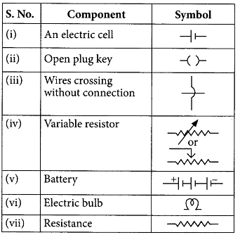
Ques. Draw the symbols of commonly used components in electric circuit diagrams for: (i) An electric cell; (ii) Open plug key; (iii) Wires crossing without connection; (iv) Variable resistor; (v) Battery; (vi) Electric bulb; (vii) Resistance (4/5, Board Term 1,2017)
Ans.
Ques. What do you infer from this V-I graph for a nichrome wire given below? Draw a labelled circuit diagram to obtain such a graph. (2020)

Ans. As graph is a straight line, so it is clear from the graph that V ∝ I.

The shape of the graph obtained by plotting potential difference applied across conductor against the current flowing v. llmuigh il will be a straight line.
According to ohms law,

V = IR or R = VI
So, the slope of V’-/ graph at any point represents the resistance of the given conductor.
For Latest Updates on Upcoming Board Exams, Click Here: https://t.me/class_10_12_board_updates
Also Read:



Comments