



Education Journalist | Study Abroad Lead
Circuit Diagrams are a graphical representation of an electric circuit by using either image of the distinct parts or standard symbols. Circuit Diagram shows the relative positions of all the elements and their connections to one another in a circuit. This topic is discussed in detail in the Current Electricity chapter of the CBSE Class 12 Physics Syllabus.
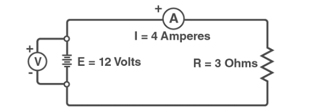
Circuit Diagram Illustration
Circuit Diagrams give a detailed understanding on the wiring connections and the components connected by them. However, the exact arrangement in the diagram may not be the same as the actual setup. Drawing a circuit diagram helps in desigining, construction, and maintainance of electrical and electronic equipments. The circuit diagram can be drawn in two ways:
- Schematic diagram
- Pictorial diagram
The article lists down some of the frequently asked choice-based questions.
Discover about the Chapter video:
Current Electricity Detailed Video Explanation:
Read More: NCERT Solutions for Class 12 Physics Current Electricity
Circuit Diagrams MCQs
Ques. Components of a circuit are shown by
- Digits
- Alphabets
- Symbols
- Scripts
Click here for the answer
Ans. The correct option is C. Symbols
Explanation: In an electrical circuit, each component has a symbol. Hence while placing the various components of the circuit in an elementary diagram, they are represented using these symbols.
Ques. Circuit diagrams is used because it helps in
- Designing
- Maintainance
- Construction
- All the above
Click here for the answer
Ans. The correct option is D. All the above
Explanation: Circuit diagrams help in designing, construction and maintainance of electrical components of an electrical circuit.
Ques. How many resistors are there in the following circuit diagram?

- 2
- 3
- 4
- 1
Click here for the answer
Ans. The correct option is C. 4
Explanation: The circuit diagram has two resistors in parallel and two in series. Hence the total number of resistors is 4.
Read More:
Ques. Identify the correct circuits from the figures provided.


Click here for the answer
Ans. The correct option is B. 
Explanation: In the figure B, the voltmeter, ammeter and the resistance are connected correctly.
Ques. Which of the following is correct in representing cells in series to get the maximum potential


Click here for the answer
Ans. The correct option is A. 
Explanation: The positive terminal of next cell is connected to the negative of the previous cell. This combination would give maximum potential. This is satisfied by figure in option A.
Ques.
A resistance is rated for 2.5 kQ, 1 watt. Determine the maximum voltage and current ratings.- 100 V, 100 mA
- 50 V, 200 mA
- 100 V, 10 mA
- 50 V, 20 mA
Click here for the answer
Ans. The correct option is D. 50 V, 20 mA
Explanation:
The formula to calculate is:
P=I2R=V2/R..........(i)
P = Power Across Resistance
I = Current
R = Resistance
V = Voltage
In the question above,
R= 2.5 K, P = 1 Watt
From equation (i)
I= \(\frac{1}{\sqrt{2500}}\)
I= 20 mA
Therefore, V = \(\sqrt{2500}\)
= 50V
Also Check Out:
Ques. Calculate Geq in the following circuit:

- 8 S
- 6 S
- 4 S
- 10 S
Click here for the answer
Ans. The correct option is C. 4 S
Explanation: According to the figure, 6S, 12 S are in series apply series combination formula and 4 S, 8S are in parallel apply parallel combination formula.
Then, Geq=(12x 6)/(12+6 )=4 S
Ques. The load of the electrical circuit is that part which:
- Supplies energy for the circuit
- Conducts current to the working device
- Converts electricity to work
- Must always be connected to a short circuit
Click here for the answer
Ans. The correct option is C. Converts electricity to work
Explanation: The load of an electrical circuit is the part that converts electricity into some form of work.
Ques. What circuit does this diagram represent:

- Series Circuit
- Parallel Circuit
- Compound Circuit
- Racing Circuit
Click here for the answer
Ans. The correct option is A. Series Circuit
Explanation: Series Arrangement refers to the arrangement of resistors in which all the resistors are connected in one line and in the above diagram all the resistors are connected in a line.
Ques. What circuit does this diagram represent:
- Complex Circuit
- Series Circuit
- Parallel Circuit
- Compound Circuit
Click here for the answer
Ans. The correct option is C. Parallel Circuit
Explanation: Parallel Arrangement refers to the arrangement of resistors in which all the resistors are connected parallel to each other and in the above circuit we can see that the resistors are connected in a parallel form.
Ques. How many current loops are there in this diagram?

- 3
- 5
- 4
- 2
Click here for the answer
Ans. The correct option is B. 5
Explanation: A current loop is a small variation in the mesh current method. The current loop is used where a device must be monitored and controlled remotely.
Ques. When the components are in series, the current passes through each component to return to a source. Therefore, should any one component, conductor become an open circuit, the current shall:
- Not flow and the circuit will fail
- The current will flow through all the components but not faulty one
- The current will flow only through the open circuit joint
- None of the above
Click here for the answer
Ans. The correct option is A. Not flow and the circuit will fail
Explanation: When the components are connected in series even if one circuit fails the whole circuit will fail.
Ques. The voltage across a number of components connected in parallel will be:
- Greater than the supply voltage
- Always same
- Equal to the sum of ever component
- Equal to 130 V
Click here for the answer
Ans. The correct option is B. Always same
Explanation: When the components are connected in parallel series the voltage is same throughout the circuit.
Also Check Out:



Comments