



Education Journalist | Study Abroad Lead
Power Transformers are used at distribution stations and electric power generating stations to step up and step down voltages. They help in reducing power loss during power transmission. Transformers are devices used for changing alternator voltage by using the principle of mutual induction. Step up and step down transformers are two types of transformers. Power transformers can be installed indoors or outdoors. Transformers are single or three -phase transformers with frequencies of 50 to 60 Hz especially when used in distribution stations.
Read More: Current Electricity
| Table of Content |
Key Terms: Transformers, Power, Electricity, Distribution, Generation, Step Up Transformer, Step Down Transformer, Current, Primary coil, Secondary coil, Mutual induction
Transformers
[Click Here for Sample Questions]
Transformer is a device used for changing the alternating voltage. The change can be to a smaller or greater value. This device follows the principle of mutual induction. A transformer includes two coils: Primary coil and secondary coil. The current passes through the primary coil and aids output in the secondary coil. The two types of transformers are:
- Step down Transformer
- Step up Transformer

Transformer Construction and Symbol
The video below explains this:
Transformer Detailed Video Explanation:
Read More:
Power Transformers
[Click Here for Previous Year Questions]
- Used at distribution stations and electric power generating stations.
- At the distribution station, a power transformer is used to step down voltages.
- At an electric power generating station, a power transformer is used to step up voltages.
- Use of power transformers in electric power systems aids in power transmission. It helps in reducing power loss.

Power Transformer
Read More: Uses of Transformers
Power Transformer Specifications
[Click Here for Sample Questions]
- Rated Power: Ranges between 3 MVA to 200 MVA
- Rated Frequency: Ranges between 50 Hz to 60 Hz
- Installation: Can be indoors or outdoors
- Tapping: Off load or on load changers
- Temperature Rise: 60 or 650C or custom specification
- Phases: Single or three- phase transformers
- Cooling type: Oil forced air forced cooling
- Typical primary voltages: 11, 22, 33, 66, 90, 132, 220 kV
- Typical secondary voltages: 3.3, 6.6, 11, 33, 66, 132 kV
- Radiators: Tank-mounted cooling radiator panels
- Vector Groups: Dyn11 or as per IEC 60076
- Voltage Regulation: Via on-load tap changer
- HV and LV Terminals: Air cable box or open bushings
- Sound Level: As per ENATS 35 or NEMA TR1 standards
Read More: Generators & Transformers
Construction of Power Transformers
[Click Here for Previous Year Questions]
The types, accessories, and design of the power transformer depend on the location, size, and application of the power transformer. Construction of Power Transformers requires basic parts like:
- Vent pipe
- Core
- Tap changing switch
- Breather
- Valves
- Thermometer
- Coil winding
- Buchholz relay
- Conservator
- Steel tank for the body of power transformer
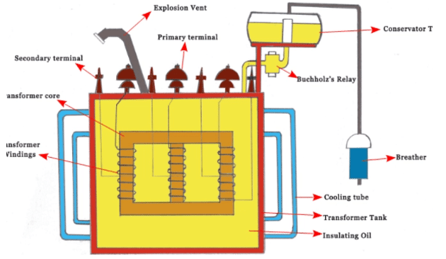
Construction of Power Transformers
Difference between Power and Distribution Transformer
[Click Here for Sample Questions]
Listed below are some common differences between power transformers and distribution transformers.
| Parameter | Power Transformer | Distribution Transformer |
|---|---|---|
| Operation | Operated in full load as it is designed for 100% efficiency. | High efficiency when load is between 50-75%. |
| Windings | Higher winding insulation due to high voltages | Winding insulation is low. |
| Size | Bulky and heavy due to high level of insulation. | Compact in comparison to power transformers. |
| Load Fluctuation | Not connected directly to homes and have less load fluctuations | Have heavy load fluctuations |
| Flux density | Higher flux density. | Low flux density |
Applications of Power Transformers
[Click Here for Previous Year Questions]
- Power transformers can be used during a high voltage step down and step up.
- They aid in reducing power loss during power transmission.
- When a full capacity load is required, power transformers are the best option.
- They help in the distribution and generation of electric power.
- Power transformers are used in isolation transformers, earthing transformers, pulse rectifier transformers, solar PV and wind farm transformers.
- Power transformers are used for long-distance consumer cases.
Read More:
Discover about the Chapter video:
Current Electricity Detailed Video Explanation:
Things to Remember
- Transformer is a device that is used to change the alternating voltage.
- Power Transformer is a type of transformer used at distribution stations and electric power generating stations.
- Some basic requirements for the construction of power transformers are core, breather, valves, tap changing switch, buchholz relay, steel tank, vent pipe, coil winding and thermometer.
- The rated power of power transformers ranges between 3 MVA to 200 MVA. It is cooled down using oil forced air cooling.
- Power transformers are the best option for a full capacity load.
Read More:
Previous Year Questions
- The core of a transformer is laminated to reduce… [KCET 2001]
- The output of a step down transformer is measured to be… [KCET 2017]
- Calculate in emf inducted in the secondary coil.
- If mutual inductance is known, calculate the emf in secondary coil.
- Quantity that remains unchanged in a transformer is?
- Rectifier converts which of the following?
- What is the coupling coefficient of a perfectly coupled coil?
- Calculate the current drawn by the primary coil of the transformer.
- Transformer is used to?
Sample Questions
Ques. Write a note on Generators. (3 marks)
Ans. The mechanical equipment that converts mechanical energy into electrical form of energy is called a Generator. Industrial and agricultural sectors often make use of generators. Generators are constructed using the principle of law of electromagnetic field. The two types of generators are AC generator and DC generator. Generators have a rectangular coil, called an armature that consists of multiple copper wires. The armature keeps changing its position over several time intervals.
Ques. How can transformers be classified based on their necessity and their location? (2 marks)
Ans. Based on their necessity, transformers can be classified into:
- Power Transformers
- Indoor Transformers
- Outdoor Transformers
- Distribution Transformers
- Measurement Transformers
Ques. Write a note on AC Generator. (3 marks)
Ans. AC generators alternate current and convert mechanical energy into electrical energy. Such generators are also known as alternators. AC generators are rated using the unit kilovolt-amperes. The two types of AC generators are Induction generators and synchronous generators. AC generators don’t require much maintenance. The losses are minimum. They are smaller in size when compared to other generators.
Ques. What are the four types of transformers? (3 marks)
Ans. The four types of transformers are:
- Step up transformer
- Step down transformer
- Power transformer
- Isolation transformer
Ques. What are the types of Transformers? (3 marks)
Ans. Commonly, there are two types of transformers: step up transformers and step down transformers. However, transformers can also be classified based on cooling methods and designs.
There are three types of transformers based on cooling method:
- Air blast type
- Oil filled water cooled type
- Oil filled self cooled type
There are two types of transformers based on design:
- Shell type transformer
- Core type transformer
Ques. Write a note on working of a transformer. (2 marks)
Ans. Working of a transformer follows the principle of mutual inductance. The two windings are close to each other but they have no conductive connection. The coil windings have magnetic induction. A sinusoidal voltage energises the primary coil winding. The secondary coil winding feeds the load. The magnetic field created transforms the energy from primary circuit to secondary circuit.
Ques. How to identify a Power Transformer? (2 marks)
Ans. A Power transformer can be identified by finding out the ratio of output voltage and input voltage which would be equal to the number of turns of the coil.
Ques. What are the uses of Transformers? (3 marks)
Ans. Transformers have a variety of uses. Some of them are:
- Transformers protect circuits from damage caused by high voltage current.
- They help in regulating the flow of current inside the circuit.
- Transformers aid in controlling the voltage so that the battery charging process is easier.
- They help in the steel manufacturing process by regulating the current for welding and melting of steel.
- Transformers are used for changing the alternating voltage.
Ques. What are the uses of Distribution and Measurement Transformers? (2 marks)
Ans. Distribution Transformers: The power generated can be distributed to distant and far away locations using distributing transformers. It can distribute power for household purposes as well as in the industries.
Measurement Transformers: Measurement Transformers help in measuring power, voltage, current, etc.
Ques. Write a note on the DC Generator. (3 marks)
Ans. DC generator converts mechanical form of energy into current electricity. The three types of DC generators are:
- Separately excited DC generators
- Permanent magnet DC generators
- Self excited DC generator
Self excited DC generators also include shunt wound generator, series wound generator, and compound wound generator.
DC generators don’t require any shielding from the radiation. Hence, the cable cost of such generators is less. The field winding determines the operating characteristics of such generators.
Ques. A source which can be represented by a voltage source of 8 V rms in series with an internal resistance of 2 kΩ is connected to a 50-Ω load resistance through an ideal transformer. Calculate the value of turns ratio for which maximum power is supplied to the load and the corresponding load power? Using MATLAB, plot the the power in milliwatts supplied to the load as a function of the transformer ratio, covering ratios from 1.0 to 10.0. (5 Marks)
Ans. For maximum power transfer, the load resistance (referred to the primary) must be equal to the source resistance.

Ques. The resistances and leakage reactances of a 30-kVA, 60-Hz, 2400-V:240-V distribution transformer are:
R1 = 0.68 Ω
R2 = 0.0068 Ω
Xl1 = 7.8 Ω
Xl2 = 0.0780 Ω
where subscript 1 denotes the 2400-V winding and subscript 2 denotes the 240-V winding. Each quantity is referred to its own side of the transformer.
a. Draw the equivalent circuit referred to (i) the high- and (ii) the low-voltage sides. Label the impedances numerically.
b. Consider the transformer to deliver its rated kVA to a load on the low-voltage side with 230 V across the load. (i) Find the high-side terminal voltage for a load power factor of 0.85 lagging. (ii) Find the high-side terminal voltage for a load power factor of 0.85 leading. (5 Marks)
Ans. 
Ques. Calculate the regulation of the transformer in which ohmic loss is 1% of the output and reactance drop is 5% of the voltage when the power factor is 0.8 lag. (5 Marks)
Ans. Voltage regulation is the change in secondary terminal voltage from no load to full load at a specific power factor of load and the change is expressed in percentage.
E2 = no-load secondary voltage
V2 = full load secondary voltage
Voltage regulation for the transformer is given by the ratio of change in secondary terminal voltage from no load to full load to no load secondary voltage.
Voltage regulation \(= \frac{{{E_2} - {V_2}}}{{{E_2}}}\)
It can also be expressed as,
Regulation \(= \frac{{{I_2}{R_{02}}\cos {ϕ _2} \pm {I_2}{X_{02}}\sin {ϕ _2}}}{{{E_2}}}\)
Regulation = %R cos ϕ ± %X sin ϕ
+ sign is used for lagging loads
- ve sign is used for leading loads
Where %R = ohmic drop
%X = reactance drop
Calculation:
Ohmic loss (%R) = 1%
Reactance drop (%X) = 5%
Power factor = cos ϕ = 0.8 lagging
∴ sin ϕ = 0.6
Regulation = %R cos ϕ ± %X sin ϕ
Ques. Compare amplifier functionality with a transformer. (4 Marks)
Ans. Transformer is used to convert low voltage (or high current) to high voltage (or low current) and high voltage to low voltage at constant power.
It works on the principle of mutual induction.
- The primary coil has Np turns. The other coil, called the secondary coil, has Ns turns.
- Generally, the primary coil works as the input coil and the secondary coil works as the output coil of the transformer.
- When an AC voltage is applied to the primary coil, the resulting current produces an alternating magnetic flux that links the secondary coil and induces an emf in it. The value of this emf depends on the number of turns in the secondary.
- In a transformer, the voltage in secondary is calculated by \(\frac{N_{s}}{N_{p}}=\frac{V_{s}}{V_{p}}\)
Here,Np and Ns are the numbers of turns in the primary and the secondary coils respectively and Vp and Vs are the RMS voltages across the primary and secondary respectively. - In a transformer, the load is connected to the secondary coil while the primary coil of a transformer is connected to an AC source.
- Mutual induction: By a change in the current in a circuit that is linked to another by the flux lines of a magnetic field, the production of an electromotive force in the circuit is called mutual induction.
Ques. Why are ferrite cores used in high frequency transformers? (3 Marks)
Ans.
- Ferrite core is a type of magnetic core made of ferrite on which the windings of electric transformers and other wound components such as inductors are formed.
- It is used for its properties of high magnetic permeability coupled with low electrical conductivity (high resistance)
- It helps in preventing eddy currents
For Latest Updates on Upcoming Board Exams, Click Here: https://t.me/class_10_12_board_updates
Check-Out:



Comments