



Content Curator
Types of DC Motors are classified into four major categories. The three types of DC Motors are:
- Separately Excited DC Motor
- Self-Excited DC Motor
- Permanent Magnet
A DC motor can be defined as a class of electrical motors which helps to convert direct current electrical energy to mechanical energy. The different types of DC motors are further classified based on the electrical connection between the rotor and stator and their ability to create field reflux.
DC Motors have unique speeds and hence find varied applications in the fields of Engineering. These motors employ DC current to transform electrical energy into mechanical energy. The major advantage of using DC motors is their compact design and ability to control speed.
Read More: Types of Motors
| Table of Content |
Key Terms: Direct Current Motor, DC, Self-Excited, Separately Excited, Permanent Magnet, Shunt, Compound Excited, Long Shunt, Short Shunt
Types of DC Motor
[Click Here for Sample Questions]
Direct Current Motor or DC Motor is a type of electric machine which converts electrical input into mechanical output.
- The Magnetic fields created by electrical currents are used in DC motors to power the movement of a rotor located within the output shaft.
- The output torque and speed are determined by the electrical input as well as the motor's design.
The types of DC Motors are given below:
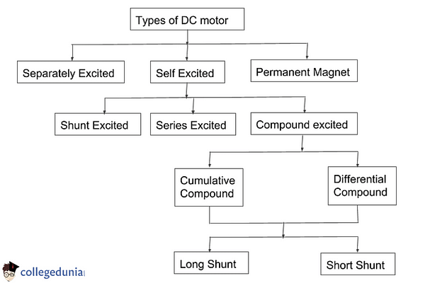
Classification of DC Motors
The types of DC motor, if listed sequentially, can be expressed as:
- Permanent Magnet DC Motor
- Shunt Motor
- Series Motor
- Compound Motor is again classified into
- Short Shunt Motor
- Long Shunt Motor
- Differentially Compound
- Cumulative Compound
DC Motor Function
According to the DC motor definition, a direct current source generates mechanical energy from an input of electrical energy.
- These devices typically possess magnetic devices, which are either permanent or electromagnetic.
- They also include a stator, armature, rotor, and commutator containing brushes.
- When an electric current is supplied via the armature or coil, a magnetic field jumps into action.
- In turn, this field is then seen to react with the installed magnet, producing a specific torque.
- Thus, a rotation in the motors can be observed.
- The commutator, here, regulates the current flow among the coils.
Read Also: Conversion of Mechanical Energy
Self-Excited DC Motor
[Click Here for Previous years Questions]
In Self-Excited DC Motors, the field winding is linked to the armature winding in series, parallel, partly in series, or partly in parallel.
It is further divided into 3 categories which are-
- Shunt-wound DC motor
- Series wound DC motor
- Compound wound DC motor
Shunt Wound DC Motor
In Shunt Wound DC Motors, the field windings are connected in parallel to the armature winding and are exposed to the entire terminal voltage in a DC motor. The field winding in a shunt-wound motor is linked parallel to the armature. Due to the fairly constant speed and medium starting torque, the shunt DC motors are usually used in industrial applications as machine tools, winding or unwinding machines, and tensioners.
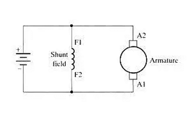
Shunt Wound DC Motor
Series Wound DC Motor
In the series wound DC motor, the field winding is connected in series to the armature winding and the entire armature current passes through it. A series DC motor has a strong starting torque and is frequently used to start high-inertia loads like trains, elevators, and hoists.
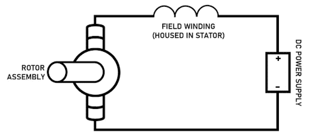
Series Wound DC Motor
Compound Wound DC Motor
The compound wound DC motor is the compound or the mixture of the shunt and the series field winding. This type of DC motor is used when high-speed torque and good speed regulation both are needed. It's further subdivided into four groups:
Cumulative Compound Motor
The flux produced by the shunt field windings decreases the effect of the main series windings in this type of compound wound DC motors. Here, \(\phi_{total} = \phi_{series} + \phi_{shunt}\).

Cumulative Compund Motor
Differential Compound Motor
The flux generated by the shunt field windings increases the effect of the main field flux generated by the series winding in differential compound motors. Here, \(\phi_{total} = \phi_{series} - \phi_{shunt}\).

Differential Compound Motor
Short Shunt DC Motor
In this, the shunt field winding is parallelly connected to the armature winding. And before being split up into the armature, the field coil, which is in series, is completely exposed to current.

Short Shunt DC Motor
Long Shunt DC Motor
In this, the shunt field winding is connected in parallel with both the series field coil and armature which are again connected in series.Compound DC motors are usually used in Rolling mills, Heavy Planers, Elevators, Shears, etc.

Long Shunt DC Motor
Read More:
| Important Topics | ||
|---|---|---|
| Electromagnetic Induction | Alternating Current | Solenoid Engine |
| AC and DC Motor | Power Transformers | Alternator Vs Generator |
Separately Excited DC Motor
[Click Here for Sample Questions]
In separately excited DC motors, the supply is given to the field and armature windings separately. The main feature of this type of DC motor is that the current through the armature doesn’t flow through the field windings because the field winding is energized by a separate DC source. This can be understood in a better way through the diagram given below.

Separately Excited DC Motor
As determined from the torque equation of DC motor, we are aware that Tg = Ka φ Ia. Thus, the torque, here, can vary by a variable field flux φ, independent of the armature current Ia.
Some key features and applications include:
- In a separately excited DC motor, the field coils are energized by an external source of DC supply.
- Separately Excited DC motor is best suited for applications that require speed variation from extremely low to very high values.
- These motors are utilized in steel rolling mills, paper machines, ship propulsion, and other applications.
Frequently Asked QuestionsQues. What happens when the speed of a DC motor increases? Ans. The back emf increases with a fall in the line currents when the speed of a DC motor increases. It is due to the speed being proportional to the back emf. In case there is a series motor, the armature current will be equivalent to the load current. Ques. How to find the direction of rotation of the motor? Ans. The direction of rotation of the motor can be decided on the basis of Fleming’s left-hand rule. It claims that when the current-carrying conductor is set in the magnetic field, a force acts on the conductor. And the other side of the given conductor which is forcefully kept under a magnetic field will produce an induced current in the conductor. |
Permanent Magnet DC Motor
[Click Here for Previous years Questions]
The permanent magnet DC Motors includes armature winding but not necessarily field windings.
- These DC motors are constructed in such a way that the radially magnetized permanent magnets are positioned on the inner periphery of the stator core for the production of the field winding.
- The rotor uses a standard DC armature with commutator segments and brushes.
- A PMDC motor’s operating voltage is 6 volts, 12 volts. It is otherwise a 24 volts DC supply acquired from the voltage sources.
- For a permanent magnet DC motor, Tg = Ka1Ia.

Permananet Magnet DC Motor
These types of DC motors offer good starting torque and good speed regulation. They are typically used in low-horsepower applications as the torque is limited in these types of DC Motors.
Applications of PMDC MotorSome PMDC Motor applications are:
|
Read More: Power of AC
Things to Remember
- DC Motors converts electrical energy into mechanical energy.
- There are mainly three types of DC motors- Self Excited, Separately excited, and Permanent magnet DC motors
- In the Self Excited DC Motors, the field winding is linked to the armature winding in series, parallel, partly in series, or partly in parallel.
- Self Excited Motors are of four types- Shunt Wound, Series Wound, and Compound Wound.
- Shunt-wound is a type of DC motor in which the field windings are connected in parallel to the armature winding and are exposed to the entire terminal voltage in a DC motor.
- In a series-wound DC motor, the field winding is connected in series to the armature winding and the entire armature current passes through it.
- The compound wound DC motor is the compound or the mixture of the shunt and the series field winding.
- In separately excited DC motors, the supply is given to the field and armature windings separately.
- The permanent magnet DC motor includes armature winding but not necessarily field windings
Also Check:
Previous Year Questions
- Direction of force in a magnetic field. [KCET 1996]
- Function of a motor. [KCET 1996]
- Calculate magnetic induction of a wire in a ciruclar loop. [KCET 2003]
- Calculate the emf indeuced across the disc. [KEAM 2006]
- Calculate propagation constant. [KCET 2021]
- Calculate the moment imparted by the light beam. [KCET 2020]
- Calculate the frequency and voltage of secondary transformer winding. [NEET 1997]
- Calculate the magnetic flux of the disc. [NEET 2008]
- Calculate the induced emf in the consucting loop. [NEET 2009]
- Relation between frequencies of different rays. [UPSEE 2016]
- Give the possible direction of electric and magnetic fields. [NEET 2021]
- Calculate the peak value of electric field strength. [VITEEE 2018]
- What is the minimum elctron density in the ionosphere. [JCECE 2007]
- What is the orientation of the current carrying coil. [VITEEE 2017]
- Calculate the magnetic field produced at the center. [NEET 2001]
Sample Questions
Ques. To what polarity do the interpoles are excited in DC motors? (1 Mark)
Ans. For motor operation, the polarity of the interpoles must be similar to the previous main pole. The direction of rotation should also be similar to that of the main poles.
Ques. Why DC motors are not operated to develop maximum power in practice? (1 Mark)
Ans. DC motors are not operated to develop maximum power in practice because the current obtained will be much higher than the rated current and due to this the efficiency of operation will be below 50%.
Ques. What type of DC motors are suitable for various torque operations? (2 Marks)
Ans. DC motors that are suitable for various torque operations are:
- DC series motor
- DC cumulatively compound motor
Ques. What are the types of DC Motors? (2 marks)
Ans. DC motors are divided into three types. They are:
- Separately Excited DC Motors
- Self-Excited DC Motors
- Permanent Magnet DC Motors
Ques. Which DC motor is the best? (2 marks)
Ans. Series wound DC Motors are the best owing to their high initial torque that can be generated wothout any sort of speed regulation. The increased voltage causes the armature and field current to rise which allows extremely high start-up torque for short periods of time.
Ques. What is the application of DC motors? (2 marks)
Ans. Electric tractions are the most vividly applied application of DC Motors.They have excellent torque properties and because of this they are widely used in traction applications. The square of the armature current is directly proportional to torque, resulting in a high starting torque.
Ques. A 10 kW DC shunt motor has the following losses at full load: Mechanical Losses = 300 W, Iron Losses = 400 W, Shunt field Cu loss = 100 W, Armature cu loss = 500 W. Calculate the full-load efficiency of the motor and armature current corresponding to maximum efficiency if the armature resistance is 0.25 Ω. (3 Marks)
Ans. Constant Losses, Wc = 300+400+100 = 800W
Variable losses = Armature culoss = 500W
Total Losses = 800+500 = 1300W
Thus, Power input, Pin = 10000+1300 = 11300W
Efficiency, η = Pout/Pin×100 = 10000/11300×100
⇒ η = 88.49%
Ques. What is the principle behind the direction of rotation of the DC motor? (3 marks)
Ans. Fleming's right-hand rule is the principle nehind the rotation of the DC Motor. Faraday's law of induction causes an electric current to be induced in a current-carrying conductor, such as a wire attached to a circuit, when it moves in a magnetic field. The thumb, first finger, and second finger of the right hand are all perpendicular to each other. The thumb is pointing in the direction of the conductor's motion relative to the magnetic field, i.e. the force direction. The forefinger is pointing in the magnetic field's direction. The direction of the induced or generated current within the conductor is represented by the middle finger. That is why Fleming’s right-hand rule. Is used to determine the direction of rotation of the DC motor.
Ques. For the same percentage increase in torque, which DC motor has the lowest percentage increase in input current for the same percentage increse in torque? (3 marks)
Ans. Series motors have the lowest percentage increase in input current. This is because the field and armature windings are connected in series, both carry the same current from the source in a DC series motor. As a result, torque is proportional to the product of field current and armature windings. The torque produced is equal to the square of the source current. So, even though there is a small change in current, the torque change is significant.
Ques. Which part helps to identify the Direct Current motor? (3 marks)
Ans. The Commutator helps identify the direct current motor. The commutator converts the alternating current generated in armature into the unidirectional current. Since it is a mechanical rectifier, the commutator collects induced EMF or the current developed in the armature. In the DC motor, the commutator is used to alternate the magnetic field created by the DC. For an AC motor the magnetic field is already alternated by the nature of the AC current.
Ques. Which DC motor should be used in an elevator? (3 marks)
Ans. Cumulative compound motor is used in an elevator. When a high starting torque or pulsating load is required, a compound motor is used. The load in the elevator is constantly pulsing, requiring a high starting torque to operate the elevator. The compound motor's series winding provides this high starting torque, while the shunt winding limits the compound motor's maximum speed at no load.
Ques. A shunt generator delivers 450 A at 230 V and the resistance of the shunt field and armature are 50 Ω and 0.03 Ω respectively. Calculate the generated e.m.f? (4 Marks)
Ans. The Generator Circuit is as shown below:
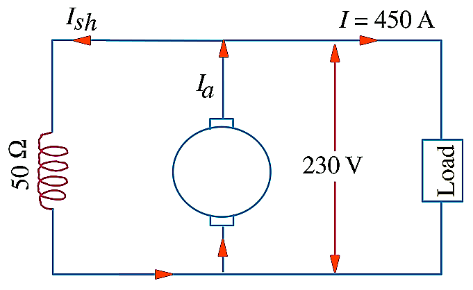
Current through shunt field winding is:
Ish= 230/50= 4.6 A
Load current, I = 450 A
Thus, Armature Current Ia = I + Ish
=450 + 4.6 = 454.6 A
Armature Voltage Drop, IaRa = 454.6 x 0.03
=13.6 V
Generated Emf, Eg = terminal voltage + armature drop
=V + IaRa
Therefore, Emf generated in armature
Eg = 230 + 13.6
=243.6 V
Ques. A 250 volt DC shunt motor has an armature resistance of 0.25 ohm on the load it takes an armature current of 50A and runs at 750rpm. If the flux of the motor is reduced by 10% without changing the load torque, find the new speed of the motor. (4 Marks)
Ans. V = 250, Ra = 0.25, Ia = 50, N1 = 750, Φ2 = 90%Φ1
\(\frac {N_2}{N_1} = \frac {E_{b2}}{E_{b1}} = \frac {\Phi_1}{\Phi_2}\)
Eb1 = V-Ia1Ra = 250-(50x0.25) = 237.5V
Eb2 = V-Ia2Ra
Load torque is constant
Ta1 = Ta2
Φ1Ia1 = Φ2Ia2
Ia2 = 55.55A
Eb2 = 250-55.55X0.25 = 236.12V
N2 = 828 rpm
Ques. A 4 pole generator with wave wound armature has 51 slots each having 24 conductors. The flux per pole is 10 mWb. At what speed must the armature rotate to give an induced emf of 0.24 kV. What will be the voltage developed, if the winding is lap connected and the armature rotates at the same speed? (4 Marks)
Ans. Given data
P = 4
No.of slots = 51
No.of conductors/slot = 20
Eg= 0.24 Kv = 240 V
Φ = 10 mW= 10/1000 Web
Total no. of conductors, Z = 51x20 = 1224
Wave winding, A=2
From EMF equation,
N= Eg60A / ΦZP = (240x60x2)/(10/1000x1224x4) = 612.75 rpm
Lap winding, A=P=4
Eg = PΦZN/60A = (4x10/1000x1224x612.75)/(60x4) = 0.125 kV
Ques. Explain the principle and parts of an electric motor (DC motor) with the help of a diagram. What is the function of a split ring commutator? (5 Marks)
Ans. A DC motor converts electrical energy into mechanical energy. It works on the principle that- a current-carrying conductor placed in a magnetic field experiences a force.
Parts of a DC Motor-
(i) Coil: It is a rectangular coil of insulated copper wire having a large number of turns.
(ii) Permanent Magnet: A large permanent magnet provides a strong magnetic field between its pole pieces. The coil rotates between these pole pieces.
(iii) Split rings: These are the two halves of Split rings. The two ends of the coil are connected to two split rings.
(iv) Brushes: Two carbon brushes are kept in contact with split rings.

DC Motor Schematic
- The split-ring commutator changes direction after every half rotation.
- The direction of current going in the coil also reverses and the arm of the coil which goes up in the first half now moves down in the second half.
- Due to this, the coil continues to rotate in one direction. Anything connected to the axis of the coil also rotates. As a result, the electrical energy given to the coil changes into mechanical energy.
For Latest Updates on Upcoming Board Exams, Click Here: https://t.me/class_10_12_board_updates
Do Check Out:



Comments